MCS Multi-display Control Module Panel User Manual MCS: Multi-display control solution 14628 Central Ave, Chino, CA 91710 tel:909.597.7588, fax:909.597.1939 © Copyright 2013 Acnodes, Inc. All rights reserved. Product description and product specifications are subject to change without notice. For latest product information, please visit Acnodes’ web site at www.acnodes.com.
Contents < Part. 1 > Interface 1.1 1.2 Connection Connection Standard < Part. 2 > Command 2.1 2.2 2.3 CAN Bus Registry Get Address Get Name 2.4 2.5 2.6 2.7 2.8 2.9 2.10 2.11 2.12 2.13 2.14 2.15 2.16 2.17 2.18 2.19 2.20 2.21 2.22 2.23 2.
< Part 1 > Interface < 1.1 > Connection - As shown in Fig. 1-1, first, connect the personal computer’s RS-232C serial port to the 1st LCD dis play’s LINK port and then begin to add connections from a LCD display, starting from the OUT port. - The first & last LCD displays located at both ends of dais y chain connection must be term inated by setting the pin 1 & 2 of DIP switch ( Set ) to ON position, located next to OUT port.
< 1.2 > Connection Standard 1) Computer to LCD display connection standard - Conducts bi-directional communication using serial RS232. - Use three signal wires of TxD, ( pin 2 ), RxD ( pin 3 ) and GND ( pin 5 ), among the RS232 standard wires, as Fig. 2-1. - Use DTR ( pin 4 ), RTS ( pin 7 ) for hot-plug detect. - The distance between the PC computer to LCD display is limited 15m.
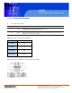
MCS Multi-display Control Module Panel < 1.2 > Connection Standard 4) The status lights ( LED ) Port Color Activity IN Green Solid LED indicates that the MSC board is powe red on. No light indica tes the board is powered off. IN Orange Blinkin g L ED indicated that the data is being transmitte d th rough the connection. No lig ht indicates no data is transmitted Table 2-1 RS-232 Communication Standards Bit Rate 9600 bps Data Bits 8 bits Parity None Stop Bits 1 bit Flow Control None Fig.
MCS Multi-display Control Module Panel < Part 2 > Command No.
< 2.1 > Detailed Description of Commands 1) CAN Bus Registry • Function The computer registers the MCS module of LCD display(s) to CAN bus daisy chain c onnection. *Registration requires when add or rem ove the LCD displays from the CAN bus connection.
MCS Multi-display Control Module Panel < 2.
MCS MCS Multi-display Control Module Panel Multi-display Control Module Panel < 2.
MCS Multi-display Control Module Panel < 2.
MCS Multi-display Control Module Panel < 2.
MCS Multi-display Control Module Panel < 2.
MCS Multi-display Control Module Panel < 2.7 > Get PIP Status • Function The computer shows the PIP setting of the LCD display The PIP function may or not be av ailable on a particular LCD display depending on the model selected • Get PIP Status Header Command 0x06, 0 x4D,0x43 • 0x07 Val 1 ID Val 2 0x00 0x00 Val 3 Val 4 Val 5 0x00 0x00 0x00 Val 3 Val 4 Val 5 Val 6 0x00 Footer Checksum 0x0D, 0 x0A Ack Header Command Val 1 ID 0x4D, 0x4 3,0x06 PIP : 0x07 PIP Val 2 P.Sour P.
MCS Multi-display Control Module Panel < 2.8 > Set Display ID • Function The computer changes the LCD display ID num ber. • Set Dis play ID number Header Command 0x06, 0x4D,0x43 0x1 5 ID Val 1 Val 2 Val 3 Val 4 Va l 5 Val 6 NewID 0x00 0 x00 0x00 0x00 0x00 Footer Checksum 0x0D, 0x0A NewID : Changes the LCD dis play’s ID to New ID number (1~64). *The new ID number will be treated as bad parameter, if the num ber is 0, 65 ~ 255 or the new ID number already occupied by other LCD display.
MCS Multi-display Control Module Panel < 2.9 > Set Display Name • Function The computer sets the name of the LCD display.
MCS Multi-display Control Module Panel < 2.10 > Show Display ID & Name • Function The LCD Display shows the ID number & name on the screen • Show Display ID and Name Header Command 0x06, 0x4D,0x43 0x17 Val 1 ID Time Val 2 0x 00 Val 3 0x00 Val 4 0x00 Val 5 0x00 Va l 6 0x00 Footer Checksum 0x0D, 0x0A Tim e : The second value for the s creen shows the display ID no.
MCS Multi-display Control Module Panel < 2.
MCS Multi-display Control Module Panel < 2.
< 2.
MCS Multi-display Control Module Panel < 2.
MCS Multi-display Control Module Panel < 2.
MCS Multi-display Control Module Panel < 2.16 > Sound Select Control • Function The computer switches the sound setting of the LCD display The PIP function may or not be available on a particular LCD dis play depending on the model selected • Set Sound Header Command 0x0 6, 0x4D,0x43 0x2 5 Val 1 ID S.S el Val 2 0x00 Val 3 0 x00 Val 4 0x00 Val 5 Val 6 0x00 0x00 Val 5 Val 6 Footer Checksum 0x0D, 0x0A S.
MCS Multi-display Control Module Panel < 2.
MCS Multi-display Control Module Panel < 2.
MCS Multi-display Control Module Panel < 2.19 > Auto Adjust Control • Function Auto adjusts the VGA picture position on the screen Available only when input sour ce is VGA • Set Auto A dust Header Command 0x06, 0 x4D,0x43 0x28 Val 1 ID A.Adj Val 2 0x00 Val 3 0x00 Val 4 Val 5 Val 6 0x00 0x00 0x00 Val 4 Val 5 Val 6 Footer Checksum 0x0D, 0 x0A A.
MCS Multi-display Control Module Panel < 2.
< 2.21 > PIP Control • Function The computer turns the PIP function of the LCD display.
< 2.22 > PIP Source Control • Function The computer adjusts the PIP source of the LCD display The PIP function may or not be available on a particular LCD display depending on the model selected Available only when PIP function is ON • Set PIP Source Header 0x06, 0 x4D,0x43 Comm and Val 1 ID 0x51 P.S our Val 2 0x00 Val 3 0x00 Val 4 Va l 5 Val 6 0x00 0x00 0x00 Footer Checksum 0x0D, 0x0A P.
MCS Multi-display Control Module Panel < 2.22 > PIP Source Control **The PIP is operable in the following table: PIP VGA S-Video Comp osite DVI-D HDMI SDI YPbPr TV VGA X O O O O O O O S-Video O X X O O O O X Composite O X X O O O O X DVI-D O O O X X O O O HDMI O O O X X O O O SDI O O O O O X X O YPbPr O O O O O X X O TV O X X O O O O X Main 14628 Central Ave, Chino, CA 91710 tel:909.597.7588, fax:909.597.
MCS Multi-display Control Module Panel < 2.23 > PIP Swap Control • Function The computer swaps the main screen with PIP screen The PIP function may or not be available on a particular LCD display depending on the model selected Available only when the PIP function is ON • Set PIP Swap Header Comm and 0x06, 0 x4D,0x43 0x52 Val 1 ID P.Swp Val 2 0x00 Val 3 0x00 Val 4 0x00 Va l 5 Val 6 0x00 0x00 Val 5 Val 6 Footer Checksum 0x0D, 0x0A P.
MCS Multi-display Control Module Panel < 2.24 > PIP Location Control • Function The computer adjusts the PIP position of the display The PIP function may or not be available on a particular LCD display depending on the m odel selected Available only when the PIP is in sm all or large size state • Set PIP location Head er Command 0x06, 0x4D,0x43 0x53 ID Val 1 Val 2 Val 3 Val 4 Val 5 Val 6 P.Loc 0x00 0x00 0x00 0x00 0x00 Val 5 Val 6 Foo ter Checksum 0x0D, 0x0 A P.