PC6172 17” industrial Core 2 Duo Panel PC User Manual PC6172: 17” Core 2 Duo touch Panel PC 14628 Central Blvd, Chino, CA91710 tel:909.597.7588, fax:909.597.1939 © Copyright 2011 Acnodes, Inc. All rights reserved. Product description and product specifications are subject to change without notice. For latest product information, please visit Acnodes’ web site at www.acnodes.com.
PC6172 Table of Contents 17” industrial Core 2 Duo Panel PC CHAPTER 1 Introduction 1-1 General Description......................................................................................................................1 1-2 System Specifications...................................................................................................................1 1-2-1 Main CPU Board......................................................................................................................
PC6172 17” industrial Core 2 Duo Panel PC 3-7 Advanced Chipset Features..........................................................................................................31 3-8 Integrated Peripherals....................................................................................................................32 3-9 Power Management.......................................................................................................................36 3-10 PnP/PCI Configuration Setup.......
PC6172 17” industrial Core 2 Duo Panel PC CHAPTER 1 INTRODUCTION 1-1 General Description Thank you for purchasing our PC6152 Intel Core 2 Duo/ Core Solo Main board enhanced with VGA/ Sound/LAN, which is fully PC/ AT compatible. The PC6152 provides faster processing speed, greater expandability and can handle more tasks than before. This manual is designed to assist you how to install and set up the system. It contains four chapters.
PC6172 1-2 System Specifications 17” industrial Core 2 Duo Panel PC - CPU: Intel® Core 2 Duo/ Core Solo/ Celeron® M Socket 478 onboard for 65nm CPU. (Up to 2.16GHz) - CHIPSET: Intel® 945GME + ICH7R (FSB: 533/667MHz) - MEMORY : 2 x 200-pin DDR2 SO-DIMM. Support DDR II 667 SDRAM up to 4GB. - CACHE : Built-in CPU. - REAL-TIME CLOCK : 256-byte battery backed CMOS RAM. Hardware implementation to indicate century rollover. - BIOS : Phoenix-AwardBIOS™ for plug & play function. 8MB with VGA BIOS.
PC6172 17” industrial Core 2 Duo Panel PC Four Analog Line-level Stereo Inputs for Connection. High Quality CD Input with Ground Sense. Stereo Line-Level Output Interface: Line-In, Line-Out, Microphone. - HARDWARE MONITORING FUNCTION : Monitor Voltage, CPU temperature, & Cooling fan speed. If CPU Temperature is over setting, the buzzer will send out a warming (only under DOS system). - IRDA PORT : 5-pin Infrared port, support IrDA v1.0 SIR protocol - GREEN FUNCTION : Controlled by hardware and software.
PC6172 17” industrial Core 2 Duo Panel PC CHAPTER 2 HARDWARE INSTALLATION 2-1 Component Locations 14628 Central Blvd, Chino, CA91710 tel:909.597.7588, fax:909.597.1939 © Copyright 2011 Acnodes, Inc. All rights reserved. Product description and product specifications are subject to change without notice. For latest product information, please visit Acnodes’ web site at www.acnodes.com.
PC6172 17” industrial Core 2 Duo Panel PC 2-2 How to Set The Jumpers You can configure your board by setting jumpers. Jumper is consists of two or three metal pins with a plastic base mounted on the card, and by using a small plastic "cap", Also known as the jumper cap (with a metal contact inside), you are able to connect the pins.So you can set-up your hardware configuration by "open" or "close" pins. The jumper can be combined into sets that called jumper blocks.
PC6172 17” industrial Core 2 Duo Panel PC JUMPER SETTINGS 2-3 COM port connector COM1 : COM1 Connector COM1 is fixed as RS-232. The pin assignment is as follows : 14628 Central Blvd, Chino, CA91710 tel:909.597.7588, fax:909.597.1939 © Copyright 2011 Acnodes, Inc. All rights reserved. Product description and product specifications are subject to change without notice. For latest product information, please visit Acnodes’ web site at www.acnodes.com.
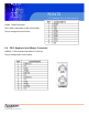
PC6172 17” industrial Core 2 Duo Panel PC COM2 : COM2 Connector The COM2 is selectable as RS-232/422/485. The pin assignment is as follows : 2-4 PS/2 Keyboard and Mouse Connector JKBMS1 : PS/2 Keyboard and Mouse Connector The pin assignments are as follows : 14628 Central Blvd, Chino, CA91710 tel:909.597.7588, fax:909.597.
PC6172 17” industrial Core 2 Duo Panel PC 2-5 Reset Connector JPANEL1 (13, 15) : Reset Connector. The pin assignment is as follows : 2-6 Hard Disk Drive LED Connector JPANEL1 (9, 11) : Hard Disk Drive LED Connector The pin assignment is as follows : 2-7 ATX Power Button JPANEL1 (14, 16) : ATX Power Button The pin assignment is as follows : 14628 Central Blvd, Chino, CA91710 tel:909.597.7588, fax:909.597.1939 © Copyright 2011 Acnodes, Inc. All rights reserved.
PC6172 17” industrial Core 2 Duo Panel PC 2-8 External Speaker Connector JPANEL1 (1, 3, 5, 7) : External Speaker Connector The pin assignment is as follows : 2-9 Power LED Connector JPANEL1 (8, 10, 12) : Power LED Connector The pin assignment is as follows: 14628 Central Blvd, Chino, CA91710 tel:909.597.7588, fax:909.597.
PC6172 2-10 Clear CMOS Data Selection 17” industrial Core 2 Duo Panel PC JP2 : Clear CMOS Data Selection The selections are as follows : *** Manufacturing Default - Keep CMOS. Note: To clear CMOS data, user must power-off the computer and set the jumper to "Clear CMOS" as illustrated above. After five to six seconds, set the jumper back to "Normal" and power-on the computer. 2-11 CPU Fan Connector FAN1 : CPU Fan connector The pin assignment is as follows: 14628 Central Blvd, Chino, CA91710 tel:909.597.
PC6172 17” industrial Core 2 Duo Panel PC 2-12 System Fan Connector FAN2: System Fan connector The pin assignment is as follows: JCFAN1: System Fan connector The pin assignment is as follows: 2-13 Hard Disk Drive Connector The PLP-P615 possesses one HDD connector: IDE1. IDE1: Hard Disk Drive Connector The pin assignments are as follows: 14628 Central Blvd, Chino, CA91710 tel:909.597.7588, fax:909.597.
PC6172 17” industrial Core 2 Duo Panel PC 14628 Central Blvd, Chino, CA91710 tel:909.597.7588, fax:909.597.1939 © Copyright 2011 Acnodes, Inc. All rights reserved. Product description and product specifications are subject to change without notice. For latest product information, please visit Acnodes’ web site at www.acnodes.com.
PC6172 17” industrial Core 2 Duo Panel PC 2-14 VGA Connector VGA1: VGA Connector The pin assignments are as follows: 14628 Central Blvd, Chino, CA91710 tel:909.597.7588, fax:909.597.
PC6172 2-15 Serial ATA Connector For Satadom 17” industrial Core 2 Duo Panel PC SATA1~SATA2: The PLP-P61x possesses two Serial ATA Connector, SATA1~SATA2. The pin assignments are as follows: SATA: SATA Connector The pin assignments are as follows: SATA2: SATA Connector The pin assignments are as follows: 14628 Central Blvd, Chino, CA91710 tel:909.597.7588, fax:909.597.1939 © Copyright 2011 Acnodes, Inc. All rights reserved.
PC6172 17” industrial Core 2 Duo Panel PC 2-16 Universal Serial Bus Connector USB1: Universal Serial Bus Connector The pin assignments are as follows: JUSB2:Universal Serial Bus Connector The pin assignments are as follows: 14628 Central Blvd, Chino, CA91710 tel:909.597.7588, fax:909.597.
PC6172 17” industrial Core 2 Duo Panel PC USB3:Universal Serial Bus Connector The pin assignments are as follows: J2:USB & LAN Connector The pin assignments are as follows: LAN: 14628 Central Blvd, Chino, CA91710 tel:909.597.7588, fax:909.597.1939 © Copyright 2011 Acnodes, Inc. All rights reserved. Product description and product specifications are subject to change without notice. For latest product information, please visit Acnodes’ web site at www.acnodes.com.
PC6172 17” industrial Core 2 Duo Panel PC LAN LED Indicator: Left side LED: Right side LED: USB Signal: 14628 Central Blvd, Chino, CA91710 tel:909.597.7588, fax:909.597.
PC6172 17” industrial Core 2 Duo Panel PC 2-18 IRDA Connector IRDA1: IrDA (Infrared) Connector The pin assignments are as follows: 2-19 ATX Power Connector PW:ATX 12V Connector The pin assignments are as follows: 14628 Central Blvd, Chino, CA91710 tel:909.597.7588, fax:909.597.1939 © Copyright 2011 Acnodes, Inc. All rights reserved. Product description and product specifications are subject to change without notice. For latest product information, please visit Acnodes’ web site at www.acnodes.com.
PC6172 17” industrial Core 2 Duo Panel PC ATXPWR: ATX Connector The pin assignments are as follows: 2-20 Sound Connector JAUDIO1: Sound Connector The pin assignments are as follows: SPDIF (inside the Line-In hole) Line-In: light blue color SPK-Out: light green color 14628 Central Blvd, Chino, CA91710 tel:909.597.7588, fax:909.597.
PC6172 17” industrial Core 2 Duo Panel PC Mic-In: pink color 2-21 LVDS Connector J1: LVDS CONNECTOR The pin assignments are as follows: 14628 Central Blvd, Chino, CA91710 tel:909.597.7588, fax:909.597.1939 © Copyright 2011 Acnodes, Inc. All rights reserved. Product description and product specifications are subject to change without notice. For latest product information, please visit Acnodes’ web site at www.acnodes.com.
PC6172 17” industrial Core 2 Duo Panel PC 2-22 LVDS Panel Voltage Selection JP4: LVDS Panel Voltage Selection. The pin assignments are as follows: *** Manufacturing Default - +3.3V. 14628 Central Blvd, Chino, CA91710 tel:909.597.7588, fax:909.597.
PC6172 17” industrial Core 2 Duo Panel PC 2-23 FSB Frequency Selection JP5, JP6, JP7:FSB Frequency Selections. The pin assignments are as follows: *** Manufacturing Default - 667 MHz. 2-24 Power State Selection JP22, JP10, JP21:Power State Selections. The pin assignments are as follows: 14628 Central Blvd, Chino, CA91710 tel:909.597.7588, fax:909.597.1939 © Copyright 2011 Acnodes, Inc. All rights reserved. Product description and product specifications are subject to change without notice.
PC6172 17” industrial Core 2 Duo Panel PC *** Manufacturing Default - ATX. *** JP21 Pin1 ~ Pin 2: Power State Selection JP21 Pin 3 ~ Pin 8: Reset/ NMI Selection 14628 Central Blvd, Chino, CA91710 tel:909.597.7588, fax:909.597.
PC6172 2-25 Reset/NMI Selections 17” industrial Core 2 Duo Panel PC JP21: Reset/ NMI Selections. *** Manufacturing Default -RESET. 14628 Central Blvd, Chino, CA91710 tel:909.597.7588, fax:909.597.1939 © Copyright 2011 Acnodes, Inc. All rights reserved. Product description and product specifications are subject to change without notice. For latest product information, please visit Acnodes’ web site at www.acnodes.com.
PC6172 17” industrial Core 2 Duo Panel PC 2-26 CF Card Master/ Slave Selections JP14:CF Card Master/ Slave Selection. The pin assignments are as follows: *** Manufacturing Default - Slave. 2-27 TV Out Connector JP1: TV OUT CONNECTOR The pin assignments are as follows: 14628 Central Blvd, Chino, CA91710 tel:909.597.7588, fax:909.597.
PC6172 17” industrial Core 2 Duo Panel PC 2-28 Memory Installation PLP-P615 CPU Card can support up to4GB in one SODIMM sockets. DRAM BANK CONFIGURATION 2-29 PCI-Express Card Selections JP9: PCI-Express Card Selection. The pin assignments are as follows: *** Manufacturing Default - PCI-E x 16. 14628 Central Blvd, Chino, CA91710 tel:909.597.7588, fax:909.597.1939 © Copyright 2011 Acnodes, Inc. All rights reserved. Product description and product specifications are subject to change without notice.
PC6172 17” industrial Core 2 Duo Panel PC CHAPTER 3 SOFTWARE UTILITIES 3-1 Introduction Enclosed with our PC6152 package is our driver utility, which may comes in a form of a CD ROM disc or floppy diskettes.For CD ROM disc user, you will only need some of the files contained in the CD ROM disc, please kindly refer to the following chart: User should remember to install the Utility right after the OS fully installed.
PC6172 17” industrial Core 2 Duo Panel PC 3-2-1 Installation of VGA Driver: To install the VGA Driver, simply follow the following steps: 1. Place insert the Utility Disk into Floppy Disk Drive A/B or CD ROM drive. 2. Under Windows 2000/XP/Vista system, go to the directory where VGA driver is located. 3. Click Setup.exe file for VGA driver installation. 4. Follow the instructions on the screen to complete the installation. 5.
PC6172 17” industrial Core 2 Duo Panel PC 3-3 Flash BIOS Update 3-3-1 System BIOS Update: Users of PLP-P61x can use the program "Awdflash.exe" contained in the Utility Disk for system BIOS and VGA BIOS update. 3-3-2 To Update VGA BIOS for LCD Flat Panel Display: As PC6152 user, you have to update the VGA BIOS for your specific LCD flat panel you are going to use. For doing this, you need two files. One is the "Awdflash.
PC6172 17” industrial Core 2 Duo Panel PC If you want to save up the original BIOS, enter "Y" and press < Enter >. If you choose "N", the following table will appear on screen. Select "Y", and the BIOS will be renewed. When you are refreshing the BIOS, do not turn off or reset the system, or you will damage the BIOS. After you have completed all the programming, the screen displays the table below: Please reset or power off the system, and then the Flash BIOS is fully implemented.
PC6172 17” industrial Core 2 Duo Panel PC 3-4 Lan Driver Utility 3-4-1 Introduction PC6152 is enhanced with LAN function that can support various network adapters. Installation programs for LAN drivers are listed as follows: For more details on Installation procedure, please refer to Readme.txt file found on LAN DRIVER UTILITY. 3-5 Sound Driver Utility 3-5-1 Introduction The Realtek ALC655 sound function enhanced in this system is fully compatible with Windows 2000, Windows XP, and Windows Vista.
PC6172 17” industrial Core 2 Duo Panel PC 3-5-2 Installation Procedure for Windows 2000/XP/Vista 1. From the task bar, click on Start, and then Run. 2. In the Run dialog box, type D:\Sound\path\setup, where "D:\Sound\pathname" refers to the full path to the source files. 3. Click on the OK button or press the ENTER key. 4. Click on the "Next" and OK prompts as they appear. 5. Reboot the system to complete the driver installation. 14628 Central Blvd, Chino, CA91710 tel:909.597.7588, fax:909.597.
PC6172 17” industrial Core 2 Duo Panel PC 3-6 Intel Chipset Software Installation Utility 3-6-1 Introduction The Intel® Chipset Software Installation Utility installs to the target system the Windows* INF files that outline to the operating system how the chipset components will be configured.
PC6172 17” industrial Core 2 Duo Panel PC 3-7 USB2.0 Software Installation Utility 3-7-1 Installation of Utility for Windows 2000/XP Intel USB 2.0 Enhanced Host Controller driver can only be used on Windows 2000 and Windows XP on Intel Desktop boards. It should be installed right after the OS installation, kindly follow the following steps: 1. Place insert the Utility Disk into Floppy Disk Drive A/B or CD ROM drive. 2. Under Windows 2000, and XP system, go to the directory where Utility Disc is located.
PC6172 17” industrial Core 2 Duo Panel PC 3-8 Watchdog Timer Configuration The Watch-dog Timer has a programmable time-out ranging from 1 to 255 minutes with one minute resolution, or 1 to 255 seconds with 1 second resolution. The units of the WDT timeout value are selected via bit[7] of the WDT_TIMEOUT register, which is located on I/O Port address 0x865h. The WDT time-out value is set through the WDT_VAL Runtime register, which is located on I/O Port address 0x866h.
PC6172 17” industrial Core 2 Duo Panel PC (2) ;-------------------------------------------------------------------------------------------------; Disable Watch-Dog Timer ;-------------------------------------------------------------------------------------------------mov dx, (800h+66h) ; Disabled Watch Dog mov al, 00h out dx, al mov dx, (800h+67h) mov al, 00h out dx, al mov dx, (800h+68h) ; Clear Status Bit mov al, 00h out dx, al 14628 Central Blvd, Chino, CA91710 tel:909.597.
PC6172 17” industrial Core 2 Duo Panel PC CHAPTER 4 AWARD BIOS SETUP 4-1 Introduction This chapter will show you the function of the BIOS in managing the features of your system. The PLP-P61x Intel® Core 2 Duo/ Core Solo Mini-ATX Motherboard is equipped with the BIOS for system chipset from Phoenix -Award Software Inc. This page briefly explains the function of the BIOS in managing the special features of your system. The following pages describe how to use the BIOS for system chipset Setup menu.
PC6172 17” industrial Core 2 Duo Panel PC 4-2 Entering Setup When the system is powered on, the BIOS will enter the Power-On Self Test (POST) routines and the following message will appear on the lower screen: PRESS TO ENTER SETUP, ESC TO SKIP MEMORY TEST As long as this message is present on the screen you may press the key (the one that shares the decimal point at the bottom of the number keypad) to access the Setup program.
PC6172 17” industrial Core 2 Duo Panel PC 4-3 The Standard CMOS Features Highlight the “STANDARD CMOS FEATURES” and press the key and the screen will display the following table: Phoenix - AwardBIOS CMOS Setup Utility Standard CMOS Features CMOS Setup screen: In the above Setup Menu, use the arrow keys to highlight the item and then use the or keys to select the value you want in each item. Date: < Month >, < Date > and .
PC6172 17” industrial Core 2 Duo Panel PC IDE Primary Master / Slave: IDE Secondary Master / Slave: The BIOS can automatically detect the specifications and optimal operating mode of almost all IDE hard drives. When you select type AUTO for a hard drive, the BIOS detect its specifications during POST, every time system boots. If you do not want to select drive type AUTO, other methods of selecting drive type are available: 1.
PC6172 17” industrial Core 2 Duo Panel PC - Normal: Maximum number of cylinders, heads, sectors supported are 1024, 16 and 63. - Large: For drives that do not support LBA and have more than 1024 cylinders. - LBA (Logical Block Addressing): During drive accesses, the IDE controller transforms the data address described by sector, head and cylinder number into a physical block address, significantly improving data transfer rates. For drives greater than 1024 cylinders.
PC6172 17” industrial Core 2 Duo Panel PC HARD DISK ATTRIBUTES: 14628 Central Blvd, Chino, CA91710 tel:909.597.7588, fax:909.597.1939 © Copyright 2011 Acnodes, Inc. All rights reserved. Product description and product specifications are subject to change without notice. For latest product information, please visit Acnodes’ web site at www.acnodes.com.
PC6172 17” industrial Core 2 Duo Panel PC 4-4 The Advanced BIOS Features Choose the ”ADVANCED BIOS FEATURES” in the main menu, the screen shown as below. Phoenix - AwardBIOS CMOS Setup Utility Advanced BIOS Features BIOS Features Setup Screen The "BIOS FEATURES SETUP" allow you to configure your system for basic operation. The user can select the system's boot-up sequence and security. A brief introduction of each setting is given below.
PC6172 17” industrial Core 2 Duo Panel PC Select Hard Disk Boot Device Priority USB FLASH DISK TYPE: Select USB device type. FIRST/SECOND/ THIRD/ OTHER BOOT DEVICE: The BIOS attempt to load the operating system from the devices in the sequence selected in these items. SECURITY OPTION: This category allows you to limit access to the system and Setup, or just to Setup. To disable security, select PASSWORD SETTING at Main Menu and then you will be asked to enter password.
PC6172 17” industrial Core 2 Duo Panel PC 4-5 Advanced Chipset Features Choose the ”ADVANCED CHIPSET FEATURES” from the main menu, the screen shown as below. Phoenix - AwardBIOS CMOS Setup Utility Advanced Chipset Features Chipset Features Setup Screen This parameter allows you to configure the system based on the specific features of the installed chipset. The chipset manages bus speed and access to system memory resources, such as DRAM and the external cache.
PC6172 17” industrial Core 2 Duo Panel PC DRAM RAS# TO CAS# DELAY: This item let you insert a timing delay between the CAS and RAS strobe signals, used when DRAM is written to, read from, or refreshed. Fast gives faster performance; and Slow gives more stable performance. This field applies only when synchronous DRAM is installed in the system. The choices are 2 and 3.
PC6172 17” industrial Core 2 Duo Panel PC 4-6 Integrated Peripherals Choose ”INTEGRATED PERIPHERALS” from the main setup menu, a display will be shown on screen as below: Phoenix - AwardBIOS CMOS Setup Utility Integrated Peripherals Integrated Peripherals Setup Screen By moving the cursor to the desired selection and by pressing the key, the all options for the desired selection will be displayed for choice.
PC6172 17” industrial Core 2 Duo Panel PC Phoenix - Award CMOS Setup Utility OnChip IDE Device Descriptions on each item above are as follows: 1. IDE HDD Block Mode Block mode is also called block transfer, multiple commands, or multiple sector read/write. If your IDE hard drive supports block mode (most new drives do), select Enabled for automatic detection of the optimal number of block read/writes per sector the drive can support 2.
PC6172 17” industrial Core 2 Duo Panel PC 0 through 4 provide successively increased performance. In Auto mode, the system automatically determines the best mode for each device. 5. SATA Mode: Set the Serial ATA configuration. When set in Advanced Host Controller Interface (AHCI) or RAID mode, the SATA controller is set to Native mode. Configuration options: [IDE] [RAID] [AHCI]. 6.
PC6172 17” industrial Core 2 Duo Panel PC Phoenix - Award CMOS Setup Utility Onboard Device Descriptions on each item above are as follows: 1. USB Controller This should be enabled if your system has a USB installed on the system board and you want to use it. Even when so equipped, if you add a higher performance controller, you will need to disable this feature. 2. USB 2.0 Controller Enable the USB 2.0 controller 3.
PC6172 17” industrial Core 2 Duo Panel PC Descriptions on each item above are as follows: 1. Onboard Serial Port 1/2 Select an address and corresponding interrupt for the first and second serial ports. 2. UART Mode Select This item allows you to select UART mode. 3. TxD, RxD Polarity Active This item allows you to determine the active of RxD, TxD WATCHDOG SUPPORT: To select watch-dog times.
PC6172 17” industrial Core 2 Duo Panel PC SOFT-OFF BY PWR-BTTN: Pressing the power button for more than 4 seconds forces the system to enter the Soft-Off state when the system has "hung". The choices are Delay 4 Sec and Instant-Off. PWRON AFTER PWR-FAIL: This item allows you to select if you want to power on the system after power failure.
PC6172 17” industrial Core 2 Duo Panel PC Phoenix - Award CMOS Setup Utility IRQ Resources Descriptions on each item above are as follows: 1. IRQ-n Assigned to: You may assign each system interrupt a type, depending on the type of device using the interrupt. MAXIMUM PAYLOAD SIZE: To select the maximum payload size of PCI Express devices.
PC6172 17” industrial Core 2 Duo Panel PC PC Health Status Setup Screen The PC Health Status Setup allows you to select whether to choose between monitoring or to ignore the hardware monitoring function of your system. -SHUTDOWN TEMPERATURE: This item allows you to set up the CPU shutdown Temperature. -CURRENT CPU TEMPERATURE: This item shows you the current CPU temperature. -VCORE: This item shows you the current system voltage. -5V / 12V : Show you the voltage of5V/12V.
PC6172 17” industrial Core 2 Duo Panel PC 4-11 Load Optimized Defaults When you press on this category, you get a confirmation dialog box with a message similar to the following: Pressing "Y" loads the default values that are factory setting for optimal performance system operations. 4-12 Password Setting User is allowed to set either supervisor or user password, or both of them.
PC6172 17” industrial Core 2 Duo Panel PC Press the < Enter > key again and the password will be disabled. Once the password is disabled, you can enter Setup freely. 4-13 Save & Exit Setup After you have completed adjusting all the settings as required, you must remember to save these setting into the CMOS RAM.
PC6172 17” industrial Core 2 Duo Panel PC 4-14 Exit Without Saving If you wish to cancel any changes you have made, you may select the "EXIT WITHOUT SAVING" and the original setting stored in the CMOS will be retained. The screen will be shown as below: Phoenix - AwardBIOS CMOS Setup Utility 14628 Central Blvd, Chino, CA91710 tel:909.597.7588, fax:909.597.
PC6172 17” industrial Core 2 Duo Panel PC APPENDIX A: EXPANSION BUS COMPACT FLASH CARD CONNECTOR PIN ASSIGNMENT The pin assignments of Compact Flash Card connector are stated below. 14628 Central Blvd, Chino, CA91710 tel:909.597.7588, fax:909.597.1939 © Copyright 2011 Acnodes, Inc. All rights reserved. Product description and product specifications are subject to change without notice. For latest product information, please visit Acnodes’ web site at www.acnodes.com.
PC6172 17” industrial Core 2 Duo Panel PC APPENDIX B: TECHNICAL SUMMARY Block Diagram 14628 Central Blvd, Chino, CA91710 tel:909.597.7588, fax:909.597.
PC6172 17” industrial Core 2 Duo Panel PC Interrupt Map 14628 Central Blvd, Chino, CA91710 tel:909.597.7588, fax:909.597.1939 © Copyright 2011 Acnodes, Inc. All rights reserved. Product description and product specifications are subject to change without notice. For latest product information, please visit Acnodes’ web site at www.acnodes.com.
PC6172 17” industrial Core 2 Duo Panel PC RTC & CMOS RAM MAP 14628 Central Blvd, Chino, CA91710 tel:909.597.7588, fax:909.597.
PC6172 17” industrial Core 2 Duo Panel PC Timer & DMA Channels Map Timer Channel Map : DMA Channel Map : I/O Memory Map Memory Map : 14628 Central Blvd, Chino, CA91710 tel:909.597.7588, fax:909.597.1939 © Copyright 2011 Acnodes, Inc. All rights reserved. Product description and product specifications are subject to change without notice. For latest product information, please visit Acnodes’ web site at www.acnodes.com.
PC6172 17” industrial Core 2 Duo Panel PC I/O Map : 14628 Central Blvd, Chino, CA91710 tel:909.597.7588, fax:909.597.