FALCON USER MANUAL
Brand of ACOEM
FALCON USER MANUAL Document reference: Name: Firmware versions: DOC3105 – December 2014 F FALCON USER MANUAL FW 1.10 www.acoemgroup.com support@acoemgroup.com Copyright © 2014, 01dB-Metravib SAS This document is the property of 01dB-Metravib SAS. Any dissemination, copying or publicising of this document, in whole or in part, is prohibited without the owner’s written authorisation.
TABLE OF CONTENT CHAPTER 1. General presentation ...................................................................................................... 7 1.1 Introduction ............................................................................................................................ 7 1.2 Safety instructions.................................................................................................................. 7 1.3 List of symbols and warning on the instrument ...................
2.11 Data management ............................................................................................................... 31 2.12 Update firmware................................................................................................................... 31 2.13 Auto test ............................................................................................................................... 31 2.14 Calibration ........................................................................
4.13.1 Picture and comment ...................................................................................................... 74 4.13.2 Generate report............................................................................................................... 74 4.13.3 Customized report .......................................................................................................... 74 CHAPTER 5. Maintenance ..................................................................................
CHAPTER 1. GENERAL PRESENTATION 1.1 INTRODUCTION We want to congratulate you on your choice and hope that you will be fully satisfied with it. For this reason, we recommend that you read carefully the present user guide and more specifically the safety instructions. FALCON is the new generation of portable data collectors for condition monitoring, vibration analysis and balancing.
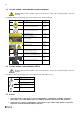
1.3 LIST OF SYMBOLS AND WARNING ON THE INSTRUMENT Warning: whenever this symbol is present on the device, refer to the safety instructions and user manuals. The table below lists the warning signs and security present on the instrument.
1.6 ELECTRIC CONNECTIONS All external circuits connected to the instrument must be non-hazardous voltage sources and be energy limited as explained in sections 6.3 and 9.4 of the IEC61010-1 standard Do not exceed maximum input voltage on the A/B/C/D connectors: maximum input voltage ±24 V DC, ±24 V AC peak. All external circuits connected to the collector must carry non dangerous voltage as defined in Standard IEC610101 (Paragraph 6.
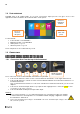
1.8 USER INTERFACE FALCON starts on its “Home screen”. It is a touch screen and a simple pressure on it gives access to the application modules installed on the instrument and to 2 side panels: Access to application modules Access to status side panel Access to shortcuts side panel For more details: Collect module: see CHAPTER 3 Balancing module: see CHAPTER 4 Status panel: see § 1.13 Shortcuts panel: see § 1.14 The 2 side panels are accessible from any screen. 1.9 CONNECTIONS 1.9.
1.9.2 Connectors E to I behind the trapdoor H G F E Those connectors are behind a trapdoor. It must remain close in industrial environment to preserve the IP65 protection. Use those connectors only in office environment. Connector E: Power supply input Connector F: Ethernet RJ45 Connector G: USB 2 type A host (for USB memory stick) Connector H: USB 2 type B device (direct connection with PC) Connector I: serial interface for maintenance purposes only 1.
1.11 WLS SENSOR FALCON can be used with a wireless triaxial accelerometer (WLS Sensor). This chapter described how to use FALCON with this sensor. 1.11.1 WLS sensor battery Use the USB cable and charger supplied with the sensor. The connector is protected by the rubber cap on the top of the sensor. It can also be charged from any USB interface with power supply (! measurement is not possible if the WLS is connected to a USB PC port). Charging time is 8 hours with the standard 500 mA charge current.
1.11.
1.12 DATA EXCHANGE WITH PC FALCON can exchange data with the PC when the Communication module is run from the home screen. See below the different settings according to the type of communication. Once the communication is established, you can also use the NEST software to upload or download routes. The instrument is also seen as an external drive from the PC (see § 6.1). 1.12.1 Using USB (Connector H) No settings are required; the PC automatically detects the instrument after its connection. 1.12.
1.12.4 Using Wi-Fi Check first if Wi-Fi is enabled in: Shortcuts > Setting > > Wi-Fi = enabled Direct Wi-Fi connection PC- FALCON setting without WLS sensor: o On FALCON: Setting > Network > Wi-Fi part Enabled = Yes Adhoc = Yes SSID = My_ONEPROD_Instrument or other Canal = 5 Authentication = none DHCP = No Set the IP address: Ex 192.168.1.16 Note: the first 3 numbers must be the same (192.168.1) and the last one different from that of the PC (14 ≠ 16) Mask = 255.255.255.
Wi-Fi LAN connection PC- FALCON setting without WLS sensor: Note: WLS sensor cannot be used simultaneously with this mode. o On FALCON: Setting > Network > Wi-Fi part Enabled: Yes Adhoc: No Save the setting Setting > Network > Wi-Fi part Scan network until you detect the right SSID Set Authentication, Encryption and Key according to selected SSID DHCP: Yes The IP address can be read in Setting > About information page.
1.13 STATUS INDICATIONS 1.13.1 Status summary The status is indicated at the bottom of the right hand side of the screen General status o Date and time o Battery level of the instrument During analogic measurement o Input overload indication in percentage of time. o Sensor integrity indicator During wireless measurement o Sensor overload indication in percentage of time. o Battery level of the sensor 1.13.
1.14 SHORTCUTS PANEL From any screen, button opens the Shortcuts panel. It gives direct access to a group of functions. The list of accessible functions depends of the current screen. 1.14.1 Photo From the Collect module, measurement list screen: take an inspection picture From Balancing module, any screen: take picture for your report (balanced machine, sensor installation, weight mounting) Take the picture: : take the picture. You must not move during few seconds. Brightness adjustment.
1.14.2 Text note From Collect module, measurement list screen: input text inspection note directly from the keyboard or from a list of predefined notes.
1.14.4 Vocal note Before using a headphone, please read the safety instructions delivered with the instrument (printed and on the CDROM) From Collect module, measurement list screen: take a vocal inspection note. Record: record your comment. Make sure you set the volume to a low level before starting to listen Play: listen to the comment For this function, you must have the optional 3.5 mm jack adapter on connector D (ref: CPC1229000 - FALCON ECTD-JACKF). 1.14.
1.14.7 Pyrometer For the pyrometer please read the safety instructions delivered with the instrument (printed and on the CDROM) From any screen, read the temperature with the built-in pyrometer Notes: from the Collect module, measurement list screen: if in Measurement setting, if “Pyrometer” = “Internal”, temperature measurement of the route with input type = DC will be done with the built-in pyrometer The pyrometer measures the average temperature in a circle.
1.14.10 Settings See CHAPTER 2. 1.14.11 Home From anywhere you can go directly to the home screen.
1.15 BATTERY MANAGEMENT For battery management, please read the safety instructions delivered with the instrument (printed and on the CDROM) 1.15.1 Battery charge When using a new battery, leave the battery in charge for about 10 hours in order to achieve full charge. Do not use the instrument prior to 2-3 hours of charge. Usual charging time is about 6 hours when instrument is switched off. Battery charge: o Connect the instrument to the charger delivered with the instrument.
Replacement instructions: o Remove the battery: Unscrew the 2 screws of the battery trapdoor. Screws Remove the connector by gently pulling the two cables. It should come off easily. In the case of an abnormal resistance, do not force and contact our after-sales service. Remove the battery. When setting up the battery, be sure to not pinch or crush the cables. Check the orientation of the battery pack. The wire output must be placed beside the connector to avoid crushing by the trapdoor.
1.16 REMOTE DISPLAY & CONTROL FUNCTION Procedure to take control of FALCON from a PC: Install Real VNC Viewer ® on the PC FALCON must be first networked by Ethernet (see § 1.12.3) or by Wi-Fi (see § 1.12.4) with the PC To work also with WLS Sensor, use the ‘Direct Wi-Fi connection PC- FALCON-WLS setting’ configuration. Run Real VNC Viewer ® Set the Input Server address: IP address of FALCON or its hostname (e.g., Falcon_10015) if there is a DNS.
CHAPTER 2. GENERAL SETUP Access: Shortcuts panel > Settings 2.1 COLLECT Possibility to protect* the modification of some route data: sensor position pictogram, location or point picture, barcode, rotation speed for measurement done by tachometer Possibility to protect* the functions ‘Delete’ and ‘Reset’ for routes not downloaded.
2.3 WIRELESS SENSOR Instructions for the first connection are presented in § 1.11.2.
2.4 T ACHOMETER First tab: Tachometer setup Adjustment of tachometer parameters: o Input range: select the range according to the tachometer signal : +/-10V, 0/-24V, 0/+24V o Coupling: DC: default setting AC: a 0.3Hz high-pass filter is applied. This can be used if the DC component of the signal is changing during measurement (for example: signal from a proximity probe during run-up / coast-down). If AC coupling is selected the automatic setup function is not accessible.
2.6 CAMERA Set the access to the barcode reader and the camera. The access to the camera can be protected by password (The protection is applied if you define a password on the last line of Settings > About). 2.7 T OUCHSCREEN Screen brightness setting Screen calibration : it may necessary to adjust the calibration. Click accurately in front of each cross appearing on the screen with a soft and thin tip, then click once more on the screen. To store the new setting, exit using function “Save” .
2.9 DATE – LANGUAGE Input of: Date: format must be DD/MM/YYYY Time: format must be HH:MM Time zone: select your time zone in the list Daylight saving: Yes or No Language: select in the list Set date and time format Date format: DD/MM/YYYY or MM/ DD/YYYY Time format: 12 or 24 2.10 NETWORK Access by network (“Remote Display and Control” function) Password: to protect remote access from a PC (see § 1.16) Remote access: Server address: input the address of the RDP server.
2.11 DATA MANAGEMENT Used to delete all data of a particular module (Collect or Balancing) or clear all the data from the instrument. Reset collect: delete all data of Collect module Reset balancing: delete all data of Balancing module Full reset: delete all data of the instrument Reset setup: return to instrument initial configuration Data are definitively deleted. Export log: create an event log file in the ‘Export’ folder. This file can be used by Acoem support for troubleshooting. 2.
2.14 CALIBRATION This screen gives information on the calibration of each channel. Sensitivity can only be calibrated by authorised personnel. An internal function ‘Offset calibration’ can be used to improve the accuracy of DC measurements. Note: for this operation, ambient temperature must be between 20 and 25°C. 2.15 BATTERY MANAGEMENT Setting of time in mn before standby and switch-off. You can set the value to disable the automatic standby or switch-off.
CHAPTER 3. COLLECTOR MODULE 3.1 INTRODUCTION The Collect module is used to run measurement programs loaded from NEST Predictive Maintenance Software. These measurement programs are commonly called Routes. Once the measurements are performed, data are downloaded to the PC for post-processing and storage in the database.
3.2 MODULE ORGANISATION Route list: see § 3.4 Acquisition: see § 3.5.2 Diagnosis: see § 3.5.4 Measurement list: see § 3.5 Measurement display: see § 3.5.3 Route exploration: see § 3.5.
3.3 SEND A ROUTE TO THE INSTRUMENT Refer to NEST or XPR documentation to see how to create a route. 3.3.1 With direct connection to the PC On FALCON: o Set the connection between PC and FALCON: see § 1.
o File name is: Route-name_Database-name_Computer-name.zld Copy the file: On a folder “Import” of a USB memory stick or Directly in the folder “Import” of the instrument memory (see § 6.1) On FALCON: o Go to “Collect” module o If you are using a USB memory stick, insert it in the port G behind the trapdoor o o Click on Import Select the route to import. 3.4 ROUTE LIST SCREEN This screen lists all the routes loaded in the instrument. The first one “OFF_ROUTE” is specific and always there.
3.5 MEASUREMENT LIST SCREEN This screen displays the points and the list of measurements to be done if the function Acquisition is used. The group of point displayed together depends on: The instrument channel number The setting of the point done on the PC The setting of the instrument For more details see § 3.5.8. Functions of the screen: Acquisition: See § 3.5.2 Previous: Go to previous group of points Next: Go to next group of points See: See the selected measurement.
Functions of the screen using the shortcuts : Inspection picture: see § 3.5.5. Inspection note: see § 3.5.5. Inspection vocal note: see § 3.5.5. Point identification with QRcode: see § 1.14.5. Listen sensor signal: see § 1.14.6. Use the pyrometer for temperature measurement: see § 3.5.6. Use the stroboscope for rotation speed measurement: see § 3.5.6.
3.5.1 Header description Measurement point or location Diagnosis indicator * Sensor pictogram** or picture **** Machine Route Measurement date Input type Main direction for vertical machine *** Notes: * Only for machine created with NEST machine setup in “Automatic diagnosis” mode and on instrument equipped with the “Diagnosis” option.
o For a single-axis measurement, a pictogram is displayed for information: For horizontal shaft: Axial (A) , Horizontal (H) , Vertical (V) and Radial oblique For vertical shaft: Axial (A) , Radial main (//) and Radial perpendicular (P or ) **** Sensor position picture: it is possible to replace the pictogram by a picture of the sensor.
3.5.2 Acquisition The instrument takes in one shot all measurements with the same input type for all the points grouped together. The channel association rules are explained in § 3.5.8. Progress bar: During the acquisition there is a succession of 2 progress bars: The acquisition itself: The bar is yellow; its duration depends on the configuration of the measurement. When this one is completed you can already remove the sensor. The processing: The bar is white.
3.5.3 See measurements This function displays the result of the selected measurement. If acquisition is not yet performed, it displays directly the live values. There are 3 types of display: Overall level Spectrum Time-wave Each one is available for 1, 2, 3 or 4 channels. For spectrum and time-wave, a first click on a curve selects it as the current one, a 2nd click sets a cursor. The cursor is automatically positioned on the maximum of the curve around the click area.
Select active cursor, central frequency or side band . Indications: At the bottom: central frequency and distance At the top: amplitude at the central frequency Zoom +: apply a zoom factor 2 around the cursor position.
3.5.4 Run automatic diagnosis This function gives directly the machine diagnosis after your measurement. This function needs that the machine is created with NEST machine setup in “Automatic diagnosis” mode and that the instrument is equipped with the “Diagnosis” option.
3.5.5 Inspection information Functions of the screen using the shortcuts: It is possible to add inspection information using functions accessible through the shortcuts panel: Inspection picture: see also § 1.14.1. The pictures are downloaded as attached to the measurement date of the machine and visible in the NEST Expertise REPORT or in XPR “Measurement information” window, “Appendix” tab. Inspection note: see also § 1.14.2.
3.5.7 Explore the route This function shows the contents of the route. Two modes are available: List mode: to see the machines of the route or the points of a machine in the order of measurement. Map mode: to see machines and sub-location positioned on the picture of their location or the point positioned on the picture of their machine in a simailar way as NEST machine supervision. Symbols used: Type of element: Location or sub-location.
Following functions are only accessible in “OFF_ROUTE” route (See § 3.7) Delete: delete the selected machine. Rename: Change the name of the selected machine. Access to OFF_ROUTE additional functions. This function is in List mode only. Create a new machine using a point template: see § 3.7.3 Copy selected machine to the clipboard. The machine can be then pasted in OFF_ROUTE Go to directly OFF_ROUTE Return to the 1st page of function.
3.5.8 Channel organisation It is possible to use FALCON with WLS sensor or with 1 to 4 wired inputs. The point to channel association depends on: Instrument setting: see § 2.2. o Wired channel number: Single or Multi o Accelerometer link: Wire or Wireless (WLS sensor) Number of optional channels of the instrument: see § 2.
The rules are the following: WLS Sensor (Accelerometer link = Wireless) o Measurement input type = Accelerometer IEPE or Accelerometer AC Measurement channel number = Multi Configuration of the points compatible with tri-axial measurement: point-channel association is done according to the sensor position pictogram. Configuration of the points not compatible with tri-axial measurement: measurement is not possible. Measurement channel number = Single: all measurements are done on sensor Z axis.
3.6 UPLOAD A MEASUREMENTS TO NEST 3.6.1 With direct connection to the PC On FALCON: o Set the connection between PC and FALCON: see § 1.12. o From FALCON home screen, select the “Communication” module: On the PC (for more details see NEST documentation) o o Run NEST software: Input your login o o Select Collect module “Collector” tab: Select “Direct transfer” and the type of connection: USB: if you connect FALCON connector H with a USB port of the PC.
3.7 OFF_ROUTE “OFF_ROUTE” is a specific route. It is used to take make measurement on machines not loaded from the PC. It is possible at any time to create a new machine by copying/pasting any machine from a standard route or from the “OFF_ROUTE” itself Expert Off_route mode (if included in the license) gives also access to the functions: Create a new machine using a point template Create a new measurement on a group of points using a template Modify the properties of a measurement.
Copy selected machine to the clipboard Paste the machine at the end of the list. If the machine already exists, 3 digits are added in the name Use this function if you want to change the name of the machine Go back to “Measurement list” screen to take measurements 3.7.
3.7.4 Create a new measurement on a group of point in Off-route From OFF_ROUTE, measurement list screen: Display additional functions Add a measurement using a template. The template measurement is selected from OFF_ROUTE route or any other routes stored in the instrument. The selection is applied on all the points of the group. Notes: For Accelerometer, Velocimeter, and Other dynamic input types, it is also possible to select if the sensor is power supplied (IEPE) or not (AC).
Input unit*: o For accelerometer: g, m/s2 o For velocimeter: in/s, mm/s o For displacement AC: mils, µm o For other input types, the unit is the same as the parameter unit. Sensitivity*: for each point of the group in mV/input unit. * only accessible for the 1st measurement of a group. The values are used for all other measurement of the group.
Parameter unit: depend on parameter: Acceleration g, m/s2 Velocity mm/s, in/s Absolute displacement µm, mils Defect factor DEF Relative displacement µm, mils Position µm, mils Rotation speed Hz, CPM Pressure Bar, PSI Flow m3/s, l/s, kg/s Temperature °C, °F Kurtosis Ku Other - 3.7.5.
Analysis: normal, synchronous If Triggering source = Free, Analysis mode is forced to Normal. For synchronous analysis, the spectrum line number is limited to 6400. Triggering mode: 1st average only, Each average For synchronous analysis, Triggering mode is forced to Each average Triggering level: Value in parameter unit Used if Triggering source = Signal Triggering slope: + or Used if Triggering source = Signal Hysteresis: Value in parameter unit Used if Triggering source = Signal.
3.7.5.
Triggering slope: + or Used if Triggering source = Signal Hysteresis: Value in parameter unit Used if Triggering source = Signal. It used to rearm the trigger system for the next acquisition and to avoid wrong triggering. Triggering delay: value in ms Used if Triggering source ≠ Free Input a negative value to have a pre-trigger. Limitations are 32K samples for pre-trigger and 2M samples for post-trigger 3.7.5.
3.7.5.7 Tabs 2 and 3 for “Defect factor” measurement type: Tab “Defect factor”: Measurement time (s): 1 to 20 Tab “Alarm”: same as for Overall Recommended values are Alarm type: High Alarm threshold: 6 DEF Danger threshold: 9 DEF 3.7.5.8 Tabs 2 and 3 for “Kurtosis” measurement type: Tab “Kurtosis”: High-pass filter*: Value in Hz Low-pass filter*: Value in Hz * High and low pass filters are keyboard inputs. High pass: from 50 Hz to half of the value of the low-pass filter.
3.7.6 How to import templates in FALCON New machines or new measurements can be added in the OFF_ROUTE route using point or measurement template from OFF_ROUTE route or any other route stored in the instrument. A template route with usual measurement examples is supplied on the CDROM in “OFF_ROUTE TEMPLATES” folder. It is available in 2 formats: Templates_EN.
CHAPTER 4. BALANCING MODULE The Balancing module enables "in situ" balancing of a rotating machine. This means that it is possible to balance the machine's rotor within its own bearings, without having to dismantle it completely and without resorting to a balancing rig.
4.1 BALANCING MODULE ORGANISATION Folder list: see § 4.2 Balancing list: see § 4.3 Report: see § 4.13 Setup: see § 4.5 Free Run: see § 4.7 Steps browser: see § 4.11 Trial Run (X Plane number): see § 4.8 Definition Measurement Balancing result: see § 4.9 Result Definition Measurement Definition Measurement Trim steps (up to 8): see § 4.
4.2 FOLDER LIST This creates a management folder used to sort balancing tests. A folder can be used to store, for example, tests on the same machine or all balancing done for a customer. Functions of the screen: Go to selected folder: see § 4.3. Create a new folder in the list. Change the name of selected folder. Delete selected folder. Return to Home screen. 4.3 BALANCING LIST This screen displays the list of balancing tests of a folder.
4.4 INSTALLING THE EQUIPMENT To perform the balancing measurements, you should have a triggering device and at least one vibration sensor available. Take care to not change the position of the sensors during the entire balancing process. 4.4.1 Vibration sensor Note: as phase measurement is required, Balancing module cannot be used with the WLS Sensor. This module does not take in account the setting: Accelerometer link: Wire or Wireless (see § 2.2).
4.4.2 Tachometer / Triggering device In order to measure the phase, an instrument must be installed, that generates an electric pulse at each rotation. Use following accessories: ACC1072000 OPT-TRG-LAS 5V PWS: optical triggering device with laser sighting CPC1228000 CABLE ECTC-M12-STR-001.5: 1.5 meter to connect it on FALCON CPC1226000 CÂBLE RALLONGE M12 5M: 5 meter cable extension 850910 OPTAPE: adhesive reflective tape.
4.5.1 Machine setup This tab gives access to following parameters: Number of planes: 1 to 4 This refers to the number of planes on which balancing weights are to be installed.
4.5.2 Measurement setup This tab gives access to following parameters: Number of channels: 1 or 2. This value is only accessible for a 2-plane balancing. If 1 is selected at each run, each point is measured one after the other one. In all other cases, the number of channels is equal to the number of planes. Number of average: 1 to 256. Advised value: 8. Measurements are obtained by averaging several successive acquisitions.
4.5.4 Units and control setup This tab gives access to following parameters: Trial weight unit: g, kg, lb, oz Radius unit: mm, cm, m, in Machine class (ISO 1940): select the machine type in the list (G0.4 to G4000). The balancing result is compared with the selected class. Machine group (ISO 10816-3): select the machine type in the list. On each measurement screen you can compare the vibration level generated by the unbalance (vibration at rotational speed) with the selected group limit.
4.7 FREE RUN After installing the vibration sensor and the tachometer, run the machine at its usual speed. This run measures the vibration at the rotation speed. Functions of the screen: Tachometer setup. Note: the free run is usually the first measurement, use this function to set tacho parameters (see § 2.4). Acquisition: wait for the machine to reach its steady state before starting the acquisition. During the acquisition, a dot is displayed for each average.
4.8 TRIAL RUN Known unbalance is added on the rotor to compute the relation between measured vibration and rotor unbalance. The number of trial runs is equal to the number of balancing planes. 4.8.1 Trial run definition You must indicate the value of the weight and its angular position in each of the balancing planes. Carefully observe the angle convention (direction of rotation = positive direction of angles). The angle unit defined in the setup is recalled on the left hand side of the input field.
Symbols used on definition screen: 1 2 Trial runs: , ,… B Balancing run: Note: Trim runs: T1 , T2 ,… 2 Negative weight is symbolized by a white square. Example: Weights of other runs are symbolized with fine borders and parentheses: 3 and 4-plane balancing is displayed in tabular mode only (2) 4.8.2 Trial run measurement Once the trial weights are installed, restart the machine. The operating mode is the same as for free run: see § 4.7.
4.9 BALANCING RESULT 4.9.1 Result After the last trial run, the instrument displays computed balancing weights. It is possible to select: The reference run: indicate the run to which balancing weights are to be added. Generally, it is either the free run (run without any trial weight), or the last run (run with all trial weights) when it is difficult or impossible to remove trial weight. Run-out: Yes or No. For measurement done with proximity probe only: see § 4.6.
4.10 TRIM STEPS The trim steps are used to iterate up to 8 additional measurements used to improve the result of the balancing. 4.10.1 Trim result This screen shows: The balancing quality grade estimation. Notes: o To display the quality, it is necessary to have the rotor weight and radius not equal to 0. o The quality is computed only for 1 or 2 plane balancing. The weights to add on the rotor to try improve the balancing quality. 4.10.
4.13 REPORT 4.13.1 Picture and comment Before generating the report, you can document the balancing with pictures and a comment. From any step of the balancing, from the shortcut panel , you can use following functions: Add a picture. You can take up to 6 pictures to document the report: global picture of the machine, sensor installation, weight installation… (see §1.14.1) Add a comment. This comment appears in the balancing report (see § 1.14.2) 4.13.
CHAPTER 5. MAINTENANCE 5.1 RESET Open the connector trapdoor. The reset button is in front of the small hole. Press it with a thin tip (a paperclip for example) during 5 or 6 seconds. The instrument restarts on the home screen. No data are deleted with this operation. 5.2 CLEANING To clean up the instrument, use only soft products (lightly soaped water). For delicate surfaces (screen, pyrometer, tachometer and laser lenses), use only clean compressed air to remove particles.
5.7 SCREEN FRAME PROTECTION A screen protection frame is supplied with FALCON. It is recommended to install it before using the instrument in an environment that can damage the screen (mainly dust). Installation instructions: If necessary, clean the screen and the area on which the frame applies. Use only a soft cloth dampened with lightly soaped water. Remove the screen film protection from the frame. Remove the film protection from the adhesive part around the screen.
CHAPTER 6. APPENDIX 6.1 APPENDIX 1: DATA STORAGE ORGANIZATION When the instrument is connected to the PC (see § 1.12), you can see the contents of its memory. The organization is as follows: ‘Balancing’: Data base including all the balancing tests ‘balancing_report_templates’: copy to this folder the customized balancing report templates ‘Collect’: there is one database for each route. It is stored in a tree structure ‘PC_server/Data_base/Route’ ‘Export’: o Measured route files (.
6.2 APPENDIX 2: SPECIFICATIONS For the main specification see FALCON technical datasheet ref TDS3143 6.2.
6.2.2 Long time-wave measurement (option) The following tables indicate the maximum number of samples and time wave duration according to: Number of simultaneous channels Analysis frequency There are two cases to consider: Each point has only 1 time wave in the measurement list (1) There is also an overall level measurement in the list (2) Depending of the configuration, if the time wave is displayed during the acquisition, the limit can be extended to the one of the previous case.
6.3 APPENDIX 2: MAIN NEW FUNCTIONS 6.3.1 Version 1.10 Each new function listed below is described in the corresponding chapter. To help you spot the upgrades of this new version within a chapter, they are written in italics. New Off-route functions (only for licence with Expert Off-route): o Function to create a machine in Off-route: see § 3.7.3 o Function to create a new measurement on a group of point in Off-route: see § 3.7.
200 chemin des Ormeaux 69578 LIMONEST – FRANCE Tel.: +33 (0)4 72 52 48 00 www.acoemgroup.com Asia Tel. +66 (2) 7112 293 – Fax +66 (2) 7112 293 South America Tel.