
User's Manual


10
Brand of ACOEM
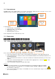
1.8 USER INTERFACE
FALCON starts on its “Home screen”. It is a touch screen and a simple pressure on it gives access to the
application modules installed on the instrument and to 2 side panels:
For more details:
Collect module: see CHAPTER 3
Balancing module: see CHAPTER 4
Status panel: see § 1.13
Shortcuts panel: see § 1.14
The 2 side panels are accessible from any screen.
1.9 CONNECTIONS
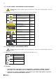
1.9.1 Connectors A to D on the top of the instrument
Those connectors can be used in industrial environment. They are IP65.
Connector A: channels 1 and 3. Use this connector when the instrument is set in single-channel mode.
Connector B: channels 2, 3 and 4. Use this connector with wired triaxial sensor when the instrument is set
in multi-channel mode.
Note: for 2-channel measurement, use connectors A and B. For 4-channel measurement, you also need Y
adaptors.
Connector C: Tachometer input, Stroboscope output, Power supply input. It it is marked in yellow as well
as all cables used on this connector
Connector D: Ethernet, Microphone input, Audio output.
Warning:
Do not connect channels 1, 2, 3, 4 and tachometer input on a not buffered output or in parallel
to other instrument as their impedance is not maintained when changing configuration or when
the instrument is switched off.
Respect the maximum input voltage to the A/B/C/D connectors: maximum input voltage ± 24 V
DC, ± 24 volts peak AC.
Access to
application
modules
Access to
status side
panel
Access to
shortcuts
side panel
A
B
C
D
Antenna for WLS
sensor and Wi-Fi