M I N I WA L L C O N T RO L L E R DMXCTRLM INSTRUCTION MANUAL Complete Integrated LED Lighting Solutions Tech Support: 212.629.
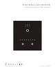
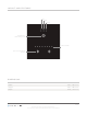
L AYO U T A N D F E AT U R E S Color Scene Dimmer Power Button / Hold to change mode Status Indicator Color, scene and dimmer adjusters DIMENSIONS Width 3.39” / 86.0 mm Height 3.39” / 86.0 mm Depth 0.39” / 10.0 mm PA G E 1 All artwork and images copyright Acolyte Industries Inc. Use or reprinting prohibited unless explicitly approved by Acolyte Industries.
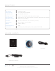
PRODUCT SPECS Input power 5 VDC to 12 VDC DMX output #1 Up to 128 channels DMX512 Available colors Frame: black or white Package contents Control unit, CD-ROM, USB cable, power supply PC requirement Mac OSX 10.7, 10.7, 10.8 | Windows XP/Vista/7, 32/64 bits and USB 2.0 Software included ESA, ESA 2 (PC & Mac) Standards EC, EMC, ROHS, ETL, UL (some are in process) Temperature 32º F to 122º F / 0º C to 50º C Weight 0.24 lb / 110.
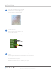
I N S TA L L AT I O N 1 2 Mount an electrical box inside the wall. The controller can be installed in any standard 60 mm electrical gang box. You can insert the AC/DC adapter inside or outside the backbox. Connect the wires. DMX: Connect the DMX cable to the external DMX interface. Power: Connect the AC/DC adapter POWER DC + POWER Ground DMX Ground DMX DMX + 3 Mount the back of the controller on the wall using 2 or more screws. Plug the green terminal block into the back of the front panel.
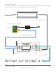
WIRING DIAGRAM W I T H D M X I N F L C D 5 A N D R G B W / R G B A R I B B O N LY T E AC Input 12 or 24V DC Output LED Driver 12 or 24 V DC from Driver to DMX Interface BACK OF MINI WALL CONTROLLER AC Input Pin 8: Ground Pin 2: Data Pin 1: Data + POWER DC+ POWER GROUND DMX GROUND 6 V DC ADAPTER DMX DMX + Cat 5 cable between DMX controller and DMX interface LED OUT 8 1 POWER IN DMX OUT 8 DMX IN 1 RJ45 Connector Pin 1: Data + Pin 2: Data Pin 8: GND INPUT: DC 12 V ~ 24 V OUTPUT: Max 20 A www