
Specifications


6
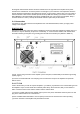
No magnetic-field sensitive devices should be located next to the right side of the amplifier as its power
transformer is located there. It's best to position it to the right of your transceiver. No temperature sensitive
devices should be located above the exhaust hot air area, so don't place it under a shelf. You may prefer to
utilize the bottom scales of both variable capacitor knobs (TUNE and LOAD) if you install it on a shelf. DO
NOT OBSTRUCT the AIR INTAKE (rear panel) and EXHAUST (top cover) areas of the amplifier. Keep a
minimum distance of 10cm (4 inches) off the intake and 50cm (20 inches) off the exhaust.
2-4. Connections
Connection to your station must be accomplished in the order described below, before you apply mains
voltage to the amplifier.
W A R N I N G
Note that the grounding system may have to withstand currents over 20A with insignificant voltage drop on it.
Therefore, it may be necessary to improve it considerably, i.e. to become less resistive, with heavier wires
and lower-resistive ground path. The grounding wires should be at least 8sq.mm (AWG 8 or SWG 10).
a) First, connect the ground stud of the amplifier (on the rear panel, marked GND) to the station's grounding
system (Fig.2-1).
b) Connect a coaxial cable with a PL-259 plug from the transceiver output to the amplifier rear panel RF
INPUT socket.
C A U T I O N
If this is the first time you will use a power amplifier in your station, pay attention to the coaxial cable type from
the amplifier's output. It must handle the increased power safely. We recommend, that you use RG213 or
better. Check the same for the antenna selector and the antenna itself.
c) Connect a coaxial cable from the amplifier output (on the rear panel, marked RF OUTPUT) with a PL-259
plug to the antenna selector or to the antenna.
d) Run a shielded cable terminated in a Phono (RCA) connector from the transceiver socket providing
"ground on transmit" to the amplifier rear panel KEY-IN socket.