
Specifications


7
Transceiver producers give different names to this output and they are for instance TX-GND, SEND, T/R-
LINE, etc. Some transceivers require that "ground on transmit" is implemented via a software command, or by
changing the setting of a switch on the rear panel, or interior of the transceiver. Check your transceiver's
manual.
N O T E
Your amplifier will not work if KEY-IN is not connected properly.
This is the T/R control input of the antenna relay. When in operate, on this input appears a 12V DC signal
which must be held to the ground by the transceiver in order to activate the amplifier. This can be done via
either a relay contact or a semiconductor - transistor or integrated circuit - having a suitable polarity (positive
to ground). You should prefer a semiconductor output when available on your transceiver, since relay
contacts on some transceiver models are slow with respect to their RF output. You may otherwise get a "Hot
Switching Warning" message. In such a case, change to the semiconductor output.
The electrical specifications of the amplifier's KEY-IN input are:
- switching voltage (open circuit): 15V max, positive to ground;
- switching current (closed circuit): 15mA max;
- voltage drop or resistance of the control output @ 15mA (closed circuit): 1.5V/250 Ohm max.
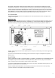
e) The KEY-OUT socket on the rear panel provides an extra control signal from the amplifier to the
transceiver. It could be used to improve the transmit/receive switching safety.
If your transceiver has a suitable input that disables transmission, we recommend that you connect it with a
shielded cable terminated in a Phono (RCA) connector to the KEY-OUT socket of the amplifier. Transceiver
producers give different names to this input and they are for instance TX-INHIBIT, MUTE, LINEAR, etc.
Check your transceiver's manual or consult your dealer.
If your transceiver does not have such an input, don't worry - the amplifier contains an independent self
protection for the antenna relay. It looks after the T/R switching to be safe, regardless of taking or not
advantage of the KEY-OUT possibility, so the amplifier will function normally, and the KEY-OUT may remain
unused as well.
The output KEY-OUT of the amplifier is an open-drain circuit and it can hold to ground a positive DC signal.
During all the periods when the amplifier is ready to transmit, this line is following the "GND on TX" request in
order to enable transceiver transmission. When transmitting is not permissible (for instance, while the
antenna relay is in process of switching-over), this output opens and the transceiver would stop driving.
The electrical specifications of the amplifier's KEY-OUT output are:
- switching voltage (open circuit): up to +50V;
- switching current (closed circuit): up to 20mA;
- resistance @ 20mA (closed circuit): 120 Ohm max.
f) Preparation of wall outlet for the amplifier.
W A R N I N G
If your amplifier is only fitted with one mains fuse, it is suitable for 0-220...240 VAC electricity supplies ONLY
(these supplies are standard in the European Community). Your dealer will check that your amplifier is
correctly fused before it is shipped to you. Customers should check with a qualified electrician if the amplifier
is to be used outside the country in which it was purchased.
Due to the different standards in different countries, the mains plug is supplied and mounted by the dealer.
He will install on the mains cable a standard mains supply plug which meets the Safety Class 1 units
standard in your country. The grounding wire of the amplifier's power cord is colored yellow with two green
stripes and the blue and brown wires are active. When the amplifier is to be used with only one mains fuse, it
is connected in series with the brown wire, which must be the active. If you have any doubts about the correct
way of connecting the wires, consult your dealer.