
Service manual

Service Manual
Functional testing
The following information gives details of how to isolate
faults to individual modules, using the dealer test disc (
0286,832) on machines which are running, but exhibiting
faults. The tests included on the disc can be divided into
two groups as follows:
• Test suite — includes everything needed for testing a
standard configuration machine. The tests run
automatically, in sequence — see the section entitled
Main PCB functional test suite on page 4-7.
• Individual tests — for testing an individual module,
expansion card, or upgrade (ie only the memory) — see
the section entitled Individual tests on page 4-15.
Note 1: Please read the section entitled The dealer test
disc before you carry out any of the tests.
Note 2: For details of how to repair the main PCB, see
Part 5 - Main PCB fault diagnosis.
The dealer test disc
This test disc (0286,832) contains various menu-driven
tests. The menus are generated from a set of text files.
You can generate new text files if you wish. The menu
option you select determines the test to be executed. To
select an option, type the corresponding letter. Some
options lead to further menus, other options run tests
immediately.
There are two types of test:
• subjective — you must judge whether the equipment
passes or fails these tests. For this reason it is a good
idea for you to familiarise yourself with the correct
results given by a known good computer. In this way
you will be in a better position to judge faulty results.
• non-subjective — the test program passes or fails the
equipment.
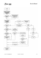
General test procedure
IMPORTANT
Before you start testing, make a backup copy of the test
discs (0286,832 and 0286,822).
All items should be complete with the correct cables so
that you can connect them to the Archimedes computer.
Safety
Some of these tests require that you remove the top
cover of the Archimedes computer. Although the power
supply unit is designed to comply with BS7002/EN60950
Class 1, you must still take care to ensure that no metal
objects fall (or are put) into the power supply unit
through the ventilation holes.
Notes:
1 You must only connect the power AFTER you have
made all the other connections.
2 You must switch off the equipment and disconnect
from the mains supply BEFORE removing any other
connections.
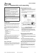
You will find instructions for removing the top cover in
Part 3 - Disassembly and assembly
Before you start
Before carrying out any of the tests in this chapter,
validate the test equipment using a known good unit. If
the test equipment fails, you should repair the test
equipment and retest on a known good unit.
Ensure that you
• adjust the colour monitor to produce adequate contrast
• inspect all the mechanical parts of the test equipment
and replace any parts as necessary.
Also, if required:
• ensure that the printer has sufficient paper
• connect the printer and monitor to the mains supply.
Do NOT turn on.
Error messages
If a message is expected and has not appeared within 30
seconds, you must record the fault, switch off the
machine and repair before retesting.
If a test fails, then you should record the fault and attempt
to continue with the tests. You should also note any other
failures, but bear in mind the possibility that these failures
could be caused by the first recorded failure.
Performing soak tests
At the end of each test, you should carry out a soak test.
To do this, leave the unit under test powered up for eight
hours, or alternatively, overnight. After carrying out the
soak test, it is advisable to retest the unit.
Repairing faults
When repairing a computer, you should repair the faults
in the order in which they occurred during the test (ie
repair the first recorded failure FIRST).
For further information on checking for component level
faults on the main PCB and carrying out repairs, refer to
Part 5 - Main PCB fault diagnosis.
4-4 Issue 2, June 1991 Part 4 - Fault diagnosis