
Service manual


Chapter 4 E20 Circuit description
FileStore Service Manual 39
4. E20 Circuit description
Read this chapter in conjunction with the circuit diagrams for FileStore E20, in Appendix C
at the back of this manual.
The only part of the E20 unit which is serviceable by Acorn dealers is the Host Adaptor pcb
(see circuit diagram) and its connectors, cables, etc. This provides an interface between the
asynchronous SCSI interface the disc controller board, and the synchronous 2MHz expansion
bus interface on the E01 unit.
The following circuit description will provide enough information about the disc controller
board and the2MHz expansion bus to allow a full understanding of the operation of the Host
Adaptor board. For a full specification of the SCSI interface see the ANSI SCSI specification
(X3.131 1986 SCSI standard and CCS document Revision 4b.)
4.1 The disc controller board
The disc controller used in the E20 unit is a device which will send or accept parallel (byte)
data to or from the host system i.e. E01 unit (via 2MHz bus and Host Adaptor), and will read
or write this data serially to or from the hard disc.
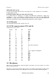
4.2 SCSI control and data lines
The 8 control and 8 data lines on the SCSI side of the controller (shown on the right side of
the Host Adaptor circuit (the initiator) diagram in the appendix) are all active-low open
collector, and are as follows:
SELECT (SEL, pin 44)
Is an open collector signal which is asserted by the initiator as the first step in any transfer of
data through the interface.
BUSY (BSY, pin 36)
Is an open collector signal which is asserted by the disc controller (the target) to indicate that
the data bus is in use. This is the first response of the target to the initiator‘s assertion of SEL,
and the SEL/BSY handshake is the first communication in any Winchester filing system
operation.
CONTROL/DATA (C/D, pin 46)
Is asserted by the target when the bus carries control information, and is deasserted when the
bus carries data.
INPUT/OUTPUT (I/O, pin 50)
Controls the direction of data flow, and is asserted by the target to indicate input to the
initiator (disc to computer), and is deasserted to indicate output to the target (computer to
disc).
REQUEST (REQ, pin 48)
Is asserted by the target to indicate a request for a REQ/ACK data transfer handshake.
ACKNOWLEDGE (ACK, pin 38)
Is asserted by the initiator to indicate acknowledgement of a REQ/ACK data transfer
handshake. The REQJACK handshake provides the asynchronous timing of all data transfer
between initiator and target.
RESET (RST, pin 40)
Is asserted by the initiator on power-up and when the host microcomputer‘s BREAK key is
pressed (if connected direct to a microcomputer). It causes the ―reset condition It which
immediately clears the bus and resets the system.