
Service manual


Chapter 5 E01S Fault finding
FileStore Service Manual 65
4. E01S Circuit description
Read this chapter in conjunction with the circuit diagrams for Stacking FileStore E01S in
Appendix D at the back of this manual.
4.1 The Central Processor
The processing power of the machine is provided by the 65C102 (IC16), an enhanced CMOS
version of the 6500 series microprocessor with its own system clocks φ2 and φ4. This
processor uses 8-bit architecture and runs at 2MHz.
Interrupts to the processor occur when either of the inputs IRQ or NMI are low. Interrupts
occur from the following sources:
IRQs from the Hard disc
NMIs from the floppy Disc Drive
NMIs from the Econet Network
IRQs from the RTC
IRQs from a printer, if connected.
The processor has no control over the first two of these interrupts, but can disable the Econet
NMIs during disc access, under software control.
Interrupts can be disabled within the RTC by writing to the interrupt enable bits in register B
(0 disables, 1 enables). Interrupts from the printer can be disabled by writing to the relevant
register within the 65C22.
The processor provides two clocks 90 degrees out of phase of each other – φ2 and φ4.
4.2 Random access memory (RAM)
Main memory is provided by two 4464s (IC9 and IC10). These are organised as 64K by 4
bits per device and together provide a 64K by 8 bit map.
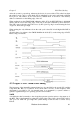
4.3 Timing
The master system clock is 8MHz, generated by IC16 together with X2, C6, CS and R16.
This is internally divided by four to produce the 2MHz phase-related timing clocks φ2 and
φ4, output on pins 39 and 3 of IC l6 respectively.
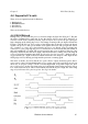
4.3.1 The Real-Time Clock (RTC)
This is a 6818 fully programmable battery-backed device that holds FileStore system
information (User id, station number, time and date etc).
The device has a multiplexed address/data bus connected directly onto the processor bus.
Data and address information is strobed in and out of the device by use of the /CE, R/W, AS
and DS signals.
When the FileStore is powered down, the /CE pin is held high by the battery backup circuitry.
This
Ceases the address/data bus, AS, DS and R/W to be disconnected within the device from the
rest of the system, hence reducing the current taken from the battery.