______________ Service Manual High Speed Combination Oven AXP5201 AXP5203 MXP5201 MXP5203 P1333603M P1333604M 50 Hz October 2010 P1333608M P1333609M 16400004 Rev.
TABLE OF CONTENTS IMPORTANT INFORMATION .....................................................................................................1 IMPORTANT SAFETY INFORMATION ................................................................................. 2-5 Oven Specifications ...............................................................................................................6 Oven Construction........................................................................................................
Important Information Important Notices for Servicers and Consumers ACP will not be responsible for personal injury or property damage from improper service procedures. Pride and workmanship go into every product to provide our customers with quality products. It is possible, however, that during its lifetime a product may require service.
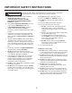
IMPORTANT SAFETY INSTRUCTIONS Commercial Microwave Ovens and Combination Ovens Important Safety Information. Read before using this oven. Keep these instructions for future reference. If the oven changes ownership, be sure this guide accompanies oven. For additional product documentation or more detailed operating instructions visit: www.acpsolutions.com CONTACT INFORMATION Any questions or to locate an authorized ACP servicer, call ACP ComServ Service Support. – Inside the U.S.A.
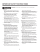
IMPORTANT SAFETY INSTRUCTIONS WARNING To reduce the risk of burns, electrical shock, fire, or personal injury when using electrical equipment, basic safety precautions should be followed. 12. DO NOT immerse cord or plug in water. 13. Keep cord AWAY from HEATED surfaces. 14. DO NOT let cord hang over edge of table or counter. 15. See door cleaning instructions on page 4. 16. To avoid risk of fire in the oven cavity: a. DO NOT overcook food.
IMPORTANT SAFETY INSTRUCTIONS CAUTION To avoid risk of personal injury or property damage, observe the following safety instructions: General Use: 1. Do not use regular cooking thermometers in oven. Most cooking thermometers contain mercury and may cause an electrical arc, malfunction, or damage to oven. 2. Never use paper, plastic, or other combustible materials that are not intended for cooking. 3.
SPECIFICATIONS Models Power Source Voltage AC Amperage (Single Unit) Frequency Single Phase, 3 Phase Receptacle Plug Power Output – Microwave Nominal microwave energy (IEC705) Minimum Temperature Rise (∆T) Operating Frequency Power Consumption Microwave only Convection fan Radiant heater Convection heater Combination Dimensions Cabinet (in / cm) Width Height Depth (includes bracket on back) Oven Interior (in / cm) – useable space Width Height Depth Weight (lbs.
OVEN OVENCONSTRUCTIONCONSTRUCTION PANELS (TOP & SIDE) Right Outer Panel Door AXP Air Filters Top Outer Panel Torx (T-15) Left Outer Panel Outercase Back Torx (T-15) 6
OVEN CONSTRUCTIONOVEN CONSTRUCTION CONTROL PANEL ASSEMBLY Control Holder Display Board Touch Screen Display Knob Collar Knob Filter Board Touch Panel Assembly Bezel Data Key Board Data Key Board Holder Data Key Plug Caution: Do not handle touch screen display by the sides. This may damage the display circuitry. Handle using the corners.
OVEN CONSTRUCTIONOVEN CONSTRUCTION Circuit Boards Power Relay Limiter Triac Thermocouple Temp Sensor (RTD) Cooling Fans Convection Motor Cavity TCO Convection Motor Main Board *Relay Monitor Board *Power Relay Snubber Power Supply Board (24 VDC) Cavity TCO Temp Sensor (RTD Radiant) Thermocouple (Limiter) Limiter Triac (TR4) -(Radiant Heater) Cooling Fans *Note: If Main Fuse (F1) is blown replace Relay Monitor Board, Power Relay & Interlock Switch Assembly.
OVEN CONSTRUCTIONOVEN CONSTRUCTION HV Transformers Magnetrons Fuses Sensor Triac’s Magnetron TCO’s Capacitor / Diodes Line Filter High Voltage Transformers Temp Sensor (RTD Convection) Small Fuses F2,F3,F4 (16 amp) F2 - Convection Motor F3 - Magnetron # 1 F4 - Magnetron # 2 Switch (Primary) Capacitor Diode (Right Side) Triac (TR1) (Magnetron # 1) Triac (TR2) (Magnetron # 2) Triac (TR3) (Convection Heater) Magnetron # 1 Large Fuses F1,F5,F6 (32 amp) Line Filter Magnetron TCO’s Magnetron # 2 Capacit
OVEN CONSTRUCTIONOven Switch Replacement & Interlock Switch Adjustment Switch Adjustment Lever Attach Ohm-Meter to Wire Harness Connectors Adjustment Figure 1 Slide Adjustment Screws When the door is opened or closed, the left door hinge activates the secondary / monitor switches. Switch Test: 1. Connect an ohm-meter to wire harness (as shown in figure 1, to verify switch activation). Note: The switch assembly should activate when the door gap is approximately 1/4 inch (6mm).
OVEN CONSTRUCTIONAntenna Motor Cam Gear Assembly Antenna Rivet, Plastic See Detail Below *Note: Plastic Rivet cannot be reused.
OVEN PERFORMANCE TEST Note: To run Oven Performance Test the, oven cavity must be at room temperature, and the display must read MICROWAVE ONLY mode. See below using oven as a microwave oven. If MICROWAVE ONLY is not in display you must go to User Options and activate MICROWAVE ONLY option. Changing User Options: 1. Oven must be OFF. 2. Press and hold Pad "2" for 5 seconds. KEYPAD 3. Rotate dial to highlight: ALLOW MICROWAVE ONLY mode. 4. Press SAVE.
OVEN PERFORMANCE TEST All Amana and Menumaster microwave oven power outputs are rated using the IEC705 standards. Using the IEC705 test method requires precision measurements and equipment that is not practical to be performed in the field. Using the test shown below will indicate if the oven performance is satisfactory. Test equipment required: • • 1000 ml test container and thermometer. Digital watch / watch with a second hand for use on ovens with electromechanical timers.
Troubleshooting POWER UP CONDITION PLUG OVEN IN (NORMAL DISPLAY) PREHEAT TEMP = 270 C PRESS TO PREHEAT 1. No Line Voltage 2. Inoperative Power Cord 3. Inoperative Fuse (F1) 4. Inoperative Touch Screen 5. Inoperative Main Control Board 6. Inoperative Display Board / Filter Board 7. Inoperative -24 Volt Power Board 8. Broken or Loose Wire Connection 9. Open Cavity TCO CHANGE TEMP PROGRAM No Yes Error Code Appears Operational Code Appears 1. Refer To Display Diagnostics Page 19 2.
Troubleshooting PREHEAT CONDITION Touch PRESS TO PREHEAT On Touch Screen or Push Knob In Yes (NORMAL DISPLAY) OVEN PREHEATING PREHEAT TEMP = 270 C Inoperative Display Board Inoperative Touch Screen No Indicates Rising Temperature PROGRAM CHANGE TEMP OVEN REACHES TEMPERATURE No Indicates Temperature Reached Yes (NORMAL DISPLAY) (NORMAL DISPLAY) MENU READY 1 2 3 4 5 6 MENU CHANGE TEMP BACK MANUAL COOK PROGRAM MANUAL COOK PREHEAT TEMP = 270 C 15 1. 2. 3. 4. 5. 6. 7. 8. 9. 10. 11.
Troubleshooting MICROWAVE CONDITION SERVICE TEST 1. Press Off Pad Repeatedly Until Press to Preheat Appears 2. Press Hidden Pad 3. Press Pads 1-3-5-7-9 Yes (NORMAL DISPLAY) SERVICE MODE OVEN INFORMATION DISPLAY VERSION: 0.39 MAIN VER: 0.46 EE 0.
Troubleshooting OPERATIONAL CODES During oven operation the display may indicate one of the following: 1. When you press the pad/ knob to preheat the oven the display indicates. 2. During cooking, the oven display indicates. CALL SERVICE 1. Unplug / plug oven in 2. If code continues to appear: a. Inoperative Electronic Limiter b. Inoperative Main Board c. Inoperative Thermocouple CODE G0 1. After food is placed in the oven the door is closed the display indicates.
Troubleshooting OPERATIONAL CODES 1. At the end of a cook cycle and the food is removed and the door is closed the display indicates. OVEN NOT AT 2. When a pad is pressed the display indicates. PREHEAT Change Option Code #10 to OFF TEMPERATURE 1. Normal do not service the oven for this. Option #12 This is activated at the factory. CLEAN It will appear every 7 days. Note: Customer can change this option as desired. See Quick Start Reference Guide section.
Display Diagnostics Error Codes Display B0 B1 Description Touch Panel Touch Panel Corrective Action Replace Touch Panel Replace Touch Panel C-0 C-1 C-2 D-0 D-1 D-2 G-0 G-2 G-2 H-0 H-1 H-2 H-3 M-0 M-1 M-2 Temp Sensor (RTD) (open) Temp Sensor (RTD) (shorted) Temp Sensor (RTD) (out of range) Thermocouple (RTD) (open) Thermocouple (RTD) (shorted) Thermocouple (RTD) (out of range) Oven Exceeded Max. Temp. Magnetron TCO Cooling Motor Signal Missing Main Board Set Point Incorrect.
AXP20 Service Test Service Test Access to Service Mode Screen While at the Main Screen, press the following sequence on the keypad: NOTE: The “MICROWAVE ONLY” button may or may not be present. 1. Press OFF pad until PRESS TO PREHEAT appears. 2. Press Hidden Pad. 3. Press pads 1 - 3 - 5 - 7 - 9 The display indicates SERVICE MODE. Hidden Pad Oven Information Screen This screen is Oven Information showing the versions of software in the control boards and information about door cycles and tube hours. 1.
Service Test 2 Manual Operation of Magnetrons #1 & #2 Screen This screen will allow operation of Magnetron #1 and #2 together and show the number of amps being drawn. NEXT TEST: Press this pad to go to the next Service Mode Test PREV TEST: Press this pad to go to the previous Service Mode Test TURN ON: This pad will toggle between turning the magnetrons on and off. CANCEL: Press this pad to return to the Main Menu RANGE: Under normal operation, each mag’s amp draw should be 5 – 12 amps.
Service Test Manual Operation of Magnetron #2 Screen This screen will allow operation of Magnetron #2 and show the number of amps being drawn. 4 NEXT TEST: Press this pad to go to the next Service Mode Test PREV TEST: Press this pad to go to the previous Service Mode Test TURN ON: This pad will toggle between turning the magnetron on and off. CANCEL: Press this pad to return to the Main Menu RANGE: Under normal operation, the amp draw should be 5 – 12 amps.
Service Test Radiant Heater Screen This screen will allow operation of the radiant heater and show the number of amps being drawn. 6 NEXT TEST: Press this pad to go to the next Service Mode Test PREV TEST: Press this pad to go to the previous Service Mode Test TURN ON: This pad will toggle between turning the heater on and off. CANCEL: Press this pad to return to the Main Menu RANGE: Under normal operation, the amp draw should be 10 – 16 amps.
Service Test Convection Fan – High Speed Screen 8 This screen will allow operation of the convection fan at a high speed and show the number of amps being drawn. NEXT TEST: Press this pad to go to the next Service Mode Test PREV TEST: Press this pad to go to the previous Service Mode Test TURN ON: This pad will toggle between turning the convection fan on and off at a high speed. CANCEL: Press this pad to return to the Main Menu RANGE: Under normal operation, the amp draw should be 0.6 – 2.6 amps.
Service Test Antenna Motor Screen This screen will allow operation of the antenna motor show the number of amps being drawn. 10 NEXT TEST: Press this pad to go to the next Service Mode Test PREV TEST: Press this pad to go to the previous Service Mode Test TURN ON: This pad will toggle between turning the antenna motor on and off. CANCEL: Press this pad to return to the Main Menu RANGE: Under normal operation, the amp draw may be to low to read.
Service Test Memory / Network Status Screen 12 This screen will show which memory chips are present and if the oven is hooked up to an external network. NEXT TEST: Press this pad to go to the next Service Mode Test PREV TEST: Press this pad to go to the previous Service Mode Test CANCEL: Press this pad to return to the Main Menu Error List Screen This screen will show a description of the types of errors that can occur.
Service Test Error History Screen This screen will show the previous error codes that have occurred in the oven. 14 NEXT TEST: Press this pad to go to the next Service Mode Test G2 PREV TEST: Press this pad to go to the previous Service Mode Test C0 H1 B0 SCROLL: This pad will advance through the history of the error codes. (1-10) CANCEL: Press this pad to return to the Main Menu Note: To clear codes: Press and hold Pad 1 until Code(s) disappear.
Calibration Touch Screen Calibration To calibrate the touch screen perform the following steps. 1. 2. 3. The oven must be plugged In. Stand-by screen must be in the Display. Press the Hidden Pad. Standby Screen □ □ Hidden Pad 4. 5. 6. 7. Press Pads 4, 5, 6. Press Directly ON small Square in the Display. The Square will move to a different location on the Display. Press Directly On the small Square in the Display again until the square disappears. Press the 0 Pad. 8.
Component Testing Procedures ! WARNING To avoid risk of electrical shock, personal injury or death; disconnect power to oven and discharge capacitor before servicing, unless testing requires power. Illustration Component Thermal cutout Thermal cutout Diode Test Disconnect all wires from TCO. Measure resistance across terminals. Control TCO ............................................. Magnetron TCO .......................................
Component Testing Procedures Illustration Component Transformer Convection blower motor ST1 Test Discharge Capacitor Remove all wires from terminals. Measure resistance from: 230 to COM.................................................. 208 to COM.................................................. 230 to Ground .............................................. 208 to Ground .............................................. Terminal 5 to 6 ............................................. Terminal 4 to Ground........
Quick Start Reference Guide Refer to Product Safety Manual for Safety Statements. High Speed Commercial Combination Oven Complete Owner’s Manual available online Cooking with Preprogrammed Pads Oven Controls To cook food using pre-programmed menu The oven touch screen displays menu options. The dial, keypad and touch screen can be used to navigate through onscreen menus. This guide will focus primarily on the dial control for menu navigation. items 1. 520° F Dial Menu Navigation 1.
Quick Start Reference Guide 1 MENU ACCESSING THE PROGRAM MENU 1. Appet-Side 2. Pasta-Pizza 3. Meats 4. Seaf-Sub 5. Dess-Soup 6. Breakfast BACK MANUAL COOK 1. To access the PROGRAM MENU, select the BACK button on the main menu screen. Push 2. Then select PROGRAM from the READY screen. High Speed Commercial Combination Oven 2 MENU 1. Appet-Side 2. Pasta-Pizza 3. Meats 4. Seaf-Sub 5. Dess-Soup 6.
Quick Start Reference Guide High Speed Commercial Combination Oven ADDING ITEM TO ITEM MENU 1. Select NEW from the PROGRAM MENU.to add a new item or EDIT to edit item. 2. Select category you wish to change from MAIN MENU and ITEM GROUP Menus. 3. At the ITEM MENU, rotate dial until until item to be added or changed is highlighted and press dial. The confirm screen will appear and ask you to confirm the change you’re making.
Quick Start Reference Guide Refer to Product Safety Manual for Safety Statements. High Speed Commercial Combination Oven Complete Owner’s Manual available online KEYPAD Changing User Options There are several option you can change to customize the operation of the oven for your business. The table below shows these options; the factory setting is shown in bold type. 1. Oven must be off. To turn oven off, press OFF button on Keypad. 2. Press and hold “2” keypad for three seconds. 3.
AXP5201, AXP5203 / MXP5201, MXP5203 EZCard Programming To program the oven using the EZCard: Oven must be in Standby mode (Preheat must be OFF) 1. Open protective cover from bottom of keypad. 2. Insert the EZCard into the slot located below the vertical keypad. Note: The EZCard can be inserted forwards or backwards. 3. From Standby, press and hold the “2” pad to go to “User Options”. 4. Go to Option #18 by pressing “Prev Option” on the screen or repeatedly pressing “Next Option” 5.
Wiring Diagram - AXP5201 P1333603M, MXP5201 P1333604M VT OR RD J3 RD P1 P2 J3 DISPLAY BOARD J1 FILTER BOARD J7 BOTTOM RADIANT HEATER J4 J6 J5 RD RD RD WH WH WH WH C BU NO MONITOR INTLK SWITCH NC GY GY BU BU CHOKE CHOKE J1 TOUCH SCREEN DISPLAY WH OR DATA KEY BOARD OR BU VT RD VT 1 2 G 1 2 G GY RADIANT HEATER TRIAC TR4 CONVECTION RTD GY RD BK RD CONVECTION HEATER TRIAC TR3 RADIANT RTD BU J2 RELAY BOARD YL BU RD RD WH WH BU OR J12 J13 J2 J1 GY BR BR OR O
37 J1 VT RD J2 4 POWER SUPPLY BOARD RD OR 0 RADIANT HEATER RELAY KEYPAD 6 J3 BU NC OR 6 GY 1 WH WH WH MONITOR INTLK SWITCH NO OR RD GY 4 WH CONVECTION HEATER RELAY DATA KEY BOARD WH 0 RD CHOKE CHOKE J2 BK RD 1 2 G GY BK BK CONVECTION HEATER TRIAC TR3 OVEN CAVITY TCO RD GY RADIANT RTD BU 1 2 G VT RADIANT HEATER TRIAC TR4 RD VT CONVECTION RTD BU RELAY BOARD J1 TOUCH SCREEN DISPLAY BU WH C RD P1 P2 J3 DISPLAY BOARD J1 FILTER BOARD GY GY WH
Schematic Diagram - AXP5201 P1333603M, MXP5201 P1333604M L1 GND L2 LINE FILTER J1-1 J1-3 J2-6,7 I2C PORT F1 J1-3 J2-1 J2-3 OVEN CAVITY TCO J13 J3-J J3-I J3-H J3-G J3-E J3-F J1 ST2-5 ST2-4 ST2-2 ST2-1 ST1-1 CONVECTION RTD DISPLAY BOARD J4-2 U8 M CONV BLOWER K1 9 7 LIMITER F5 J5-6 TC 4 J5-3 U10 J8-8 CONVECTION HEATER (TOP) CHOKE J5-4 J14-1 J8-7 6 CONTROL 3 J14-2 J7-2 T1 T2 U19 10 N.O.
Schematic Diagram - AXP5203 P1333608M, MXP5203 P1333609M L3 L2 L1 GND N J1-1 LINE FILTER J1-3 J2-6,7 F6 I2C PORT F1 J1-3 J2-1 J2-3 OVEN CAVITY TCO J13 J3-J J3-I J3-H J3-G J3-E J3-F DISPLAY BOARD J4 J3 ST2-5 ST2-4 ST2-2 ST2-1 ST1-1 CONVECTION RTD TOUCHSCREEN DISPLAY J7 FILTER BOARD MAG TCOs J4-2 J4-1 ANTENNA MOTORS ST1-2 M CONV BLOWER J7-1 J5-5 6 CONTROL 3 TC 4 LIMITER J14-1 J8-7 K2 J7-2 T1 T2 U19 10 N.O.
50 Hz High Speed Combi – AXP5201 / AXP5203 October 2010 16400004 Rev.