
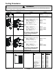
Operating instructions


Disassembly Procedures
To avoid the risk of electrical shock, personal injury, or death,
disconnect power to oven and discharge the capacitors before
following any disassembly procedure.
30 16400005 ©2009 ACP Inc.
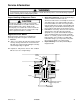
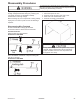
Interlock Assembly
Primary switch is operated by the top latch arm.
Interlock Switch Removal
1. Disconnect power to oven and remove outer case,
(see "Outer Case" procedure).
2. Remove control panel, (see "Control Panel" section).
3. Remove mounting screws securing interlock switch
to unit chassis.
4. Disconnect and label wire connections.
NOTE: After repairing the door or the interlock system,
it is necessary to check the switch continuity
before operating the oven.
Before replacing a blown monitor fuse, test the
primary interlock switch, secondary interlock switch,
monitor switch, and power relay contacts for proper
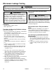
Adjusting Interlocks
The interlock monitor, primary, and secondary switches
act as a nal safety switch, protecting the operator from
microwave energy. After adjusting the interlock switch
assembly, verify wires are correctly connected.
For door t and switch operation, switch bracket is
adjustable.
1. Disconnect power to oven and remove outer case,
(see "Outer Case" procedure).
2. Loosen switch bracket mounting screws.
3. Close oven door, move switch bracket toward rear of
oven until door gap is less than
1
/64–inch (0.5 mm).
4. Hold switch bracket securely for proper switch
operation and door t, retighten screws.
5. Open oven door slowly, watching the switches. Verify
switches release in the following order.
• Primary interlock switch
• Secondary interlock switch
• Interlock monitor switch
NOTE: Adjust the switch bracket until all switches
operate in proper sequence.
6. Close the oven door slowly, watching the switches.
Verify switches activate in the following order.
• Interlock monitor switch
• Secondary interlock switch
• Primary interlock switch
7. When proper switch sequence has been achieved,
tighten the switch bracket securely.
A microwave leakage test must be preformed anytime
a door assembly is removed, replaced, disassembled,
or adjustment of switch bracket is performed.
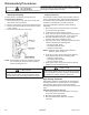
High Voltage Capacitor
High voltage capacitor should always be discharged by
shorting a terminal to a chassis ground. The capacitor
has a internal "shunt" resistor, but the mechanical
discharge should always be performed to avoid personal
injury.
High Voltage Capacitor Removal
1. Disconnect power to oven and remove outer case,
(see "Outer Case" procedure).
2. Discharge high voltage capacitor.
3. Remove and label wire leads from capacitor
terminals.
CAUT IO N
CAUT IO N