R Commercial Service / Training Manual High Speed Combination Oven AXP / MXP - 60 Hz MXP22QT December 2011 16400012 Amana® is a Registered Trademark of Maytag Corporation. Brand used under license.
6SHFL¿FDWLRQV 2YHQ 3HUIRUPDQFH 7HVW $;3 0;3 $;3 0;3 'LVSOD\ 'LDJQRVWLFV $;3 0;3
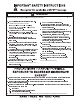
1 Important Safety Information
Important Information Important Notices for Servicers and Consumers ACP will not be responsible for personal injury or property damage from improper service procedures. Pride and workmanship go into every product to provide our customers with quality products. It is possible, however, that during its lifetime a product may require service.
Important Safety Information ! WARNING Read the following information to avoid possible exposure to microwave radiation: The basic design of the Microwave Oven makes it an inherently safe device to both use and service. However, there are some precautions which should be followed when servicing the microwave to maintain this safety. These are as follows: 1. Always operate the unit from an adequately grounded outlet. Do not operate on a two-wire extension cord. 8.
! 6 * ? WARNING ? HOHFWULFDO VKRFN ¿UH RU LQMXU\ WR SHUVRQV LQFOXGLQJ WKH IROORZLQJ " ' ( ) * B 5($' $1' )2//2: WKH VSHFL¿F + , ' ( - . / 0 1 .
WARNING WARNING 7R DYRLG ULVN RI ¿UH LQ WKH RYHQ FDYLW\ ) / 0 / .
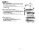
2 AXP20 / MXP20, AXP22 / MXP22 60 Hz Specifications Installation · Unpacking the oven · Oven Clearances Power Specification · Input · Output · Consumption Dimensions · Weight
STEP 1 - Unpack Oven A 5HSRUW DQ\ GHQWV RU EUHDNDJH WR VRXUFH RI SXUFKDVH LPPHGLDWHO\ 'R QRW DWWHPSW WR XVH RYHQ LI GDPDJHG 5HPRYH DOO SDFNLQJ PDWHULDOV IURP RYHQ LQWHULRU ,I RYHQ KDV EHHQ VWRUHG LQ H[WUHPHO\ FROG DUHD ZDLW D IHZ KRXUV EHIRUH C B STEP 2 - Place Oven on Counter 5HFRPPHQGHG FRXQWHUWRS VXUIDFH GHSWK
6SHFL¿FDWLRQV $;3 0;3 $;3 0;3 Power Source Voltage AC Amperage (Single Unit) Frequency Single Phase, 3 wire grounded Receptacle Plug Power Output – Microwave Nominal microwave energy (IEC705) 0LQLPXP 7HPSHUDWXUH 5LVH ¨7 Operating Frequency Power Consumption Microwave only Convection fan Radiant heater Convection heater Combination Dimensions Cabinet (in / cm) Width Height Depth (includes bracket on back) Oven Interior (in / cm) – useable space Width Height Depth Weight (lbs.
3 AXP20 / MXP20, AXP20/ MXP22 60 Hz Quick Start Reference Guide
$;3 0;3 µ ¶ · ¶ ¸ ¹ º » ¸ º ¼ ½ ¾ ¹ ¿ À · ¶ ¹ Á Â À Ã ½ À Ä · º High Speed Commercial Combination Oven ¸ ¿ À · ¶ ¹ Á ¿ ¹ À ¹ ¶ Å ¶ Ã ¹ Æ Ç È É Ê Ë Ì Í Î Í Ï Ð Ñ Í Ò Ó Ô Õ Ö Ñ × Ö Ì Ö Ø Ö Ù Ì Ö Ú Ì Í É Ñ Ì Ù Ñ Í Cooking with Preprogrammed Pads Oven Controls . ´ ~ } Û .
$;3 0;3 High Speed Commercial Combination Oven 1 ACCESSING THE PROGRAM MENU { | ~ £ ~ | ò { | ~ £ à ~ £ ³ | ³ ± } ð ² Ü ~ ~ £ ³ | MENU Push MANUAL COOK BACK ² 2 1. Appet-Side 2. Pasta-Pizza 3. Meats 4. Seaf-Sub 5. Dess-Soup 6.
$;3 0;3 High Speed Commercial Combination Oven ADDING ITEM TO ITEM MENU 4 ! ' & " % # " $ 5 6 % & ' 7 ( & 1 ) 4 4 * + , ' * - . . " ! / & 0 1 1 0 2 3 Push 8 = 0 2 ( 1 1 6 - 0 1 7 " 9 . 6 0 1 & , 7 " & : * ( 2 ; 3 ) " 0 & / . : + . % % . ! 9 / 4 > 1 < ( 2 % 4 < & ; & < 4 9 ( 0 2 9 $ % & ' . - 6 ! .
$;3 0;3 High Speed Commercial Combination Oven e f g f h i j k h j l m n i o p g f i q r p s m p t g j h o p g f i q o i p i f u f s i v w x y z { | } ~ } } | | | } y | } KEYPAD ¡ ¢ ² £ ® · ® ¼ ® ¤ ¥ ³ ½ ¡ ° £ ¤ ¡ ¡ ¡ ¬ ¹ ¬ · ¦ £ ± ¥ ¢ ¦ ¡ ¡ £ £ ¢
$;3 0;3 To program the oven using the EZCard: Oven must be in Standby mode (Preheat must be OFF) 1. Open protective cover from bottom of keypad. 2. Insert the EZCard into the slot located below the vertical keypad. Note: The EZCard can be inserted forwards or backwards. 3. From Standby, press and hold the “2” pad to go to “User Options”. 4. Go to Option #18 by pressing “Prev Option” on the screen or repeatedly pressing “Next Option” 5.
7RXFK 3DQHO 6\PERO 'HVFULSWLRQ $;3 0;3 Ç ¥ ¡ ¤ © ¤ £ ¨ ¡ ¥ £ ¥ ¨ ¡ § ¥ © ± ¡ ¤ ¡ ¯ ¯ ¥ ¢ ¨ ¤ ¦ ª ¥ § ¥ ª § ¨ ¥ ± £ § ¡ ¤ ¨ ® ¡ § © ¡ § £ £ 21 2)) .
7RXFK 3DQHO 6\PERO 'HVFULSWLRQ $;3 0;3 " ! 2YHQ &RROLQJ 0RGH ,FRQ Ç × Ô Ó Ó à Ø Ö á Û Ü ã Ô Ó Ô à à â Ü ã Ø × ÿ Ø û Ô ü Ú à Ø ú à Û Ü Ø à á Ô × Ó Ô à à â Ü ã á × Ô Ó Ó à Ø ÿ Ø û û Ô Ü Ø û Ô Ô Û × Ó Ú Ô × Û ä Ü å Ç Û Ü ß á Ô Ø â Ô ü Ú à Ø Û Ü Ø à á Ô × á â ã á Ù â ã á à Ô Ù Ö Ô Ø Ü Ü à â Ü Ø ü Ø Ô Ù â à Ü Ø × ã ü Ü Ø % à Ý Ø Ö Ô
$;3 0;3 High Speed Commercial Combination Oven e f g f h i j k h j l m n i o p g f i q r p s m p t g j h o p g f i q o i p i f u f s i v w x y z { | } ~ } } | | | } y | } Ç ¥ ¡ ¤ © ¤ ¥ £ ¨ ¡ £ ¥ ¨ ¡ § ¥ © ± ¡ ¤ ¡ ¯ ¢ ¥ ¯ ¨ ¤ ¦ ª ¥ § ¥ ª § ± ¡ ¥ £
$;3 0;3 High Speed Commercial Combination Oven ä & Ú à × Ô × Ô à Ú × Û á Ô Ø Ø ã ÿ × Ú Ù û Û Ô ÿ Ô Ü á ÿ Ó Û Ô Ø ä Ú ß × MAIN COOKING MENU Ó Ý Ô â Ú × à × Ô á á Ô Ó Ø ã Û Ô × û Û à Ô Ô Ý × ÿ ÿ à - Û Ù Ô Ý á ÿ Ô Ô ÿ Ü Ô % Ô ü â Ü Ü à ü Ô ü Û ÿ à + Ú Ó Ô à ÿ Ú Ô Ø Û Ó Ó Ü + × â Ó å ÿ Ö Ú Ù ü Ç Ù Ý â á ä Ô Ô Ö Ø Ø û Ø Ô Ü â Ü Ö ã Ø ÿ Ô Ó å V ú 0HDW
$;3 0;3 High Speed Commercial Combination Oven Using MANUAL COOK } ~ 8VH 0DQXDO FRRNLQJ ZKHQ D VSHFL¿F WLPH DQG FRRNLQJ SRZHU OHYHOV DUH GHVLUHG ,W¶V YHU\ XVHIXO ZKHQ \RX DUH W ± « å ± ä & ¢ ° à Ô × Ø û Ô ª Ü á ¡ ² Û ©
$;3 0;3 High Speed Commercial Combination Oven ACCESSING THE PROGRAM MENU Ü © å [ × Ô Ó Ó à á Ô Ü à Ô × Ô Ú Û Ý Û Ü Ý Ö Ø Ø Ó Ô à à â Ü ã Ó ß â Ù Ù à £ ¥ § § ¢ ¢ é ¯ ê ¯ º ¤ ¡ ¬ ¢ ¢ ú Û é ¥ ¨ » ¥ ¡ Ú Ú Û × å £ å µ Õ ë Ô Ò Ô Ù Ô Ó Ö Ô à Õ Ç Ö Ô × ÿ Ø Ú Ù Ô Ù Ò × Ú Û à Ø ü × Ô Ç - â × Õ ÿ Ô Ö × - Ø Ù â % Ù Ö Þ × Ø Ø ß
$;3 0;3 High Speed Commercial Combination Oven ,,, (GLWLQJ $GGLQJ 1DPH LQ 0HQX ,WHP EDITING OR ADDING NEW NAMES FOR MENU CATEGORY OR FOOD CATEGORY OR MENU ITEM ® ¡ ¥ ¡ ¡ ¥ ¢ ¢ ¬ » ¦ ¦ ¢ ¥ » ¦ ¿UVW ç º © £ é ¢ ¢ é ¥ ¨ » ¥ ¡ £ ñ ± ¡ ¢ ¡ ¤ ¦ ¥ » £ ë è £ ¨ ñ » ¥ ± ¡ ¥
$;3 0;3 High Speed Commercial Combination Oven Ü Ü ¢ ¥ ¢ « ¢ ¥ ± ¥ § ¢ » » ¦ ¢ § ¥ § ¢ ¥ ¢ § ¦ ¢ ° ± ¡ » ¥ « » ¦ ° ¦ ¢ ¢ ¢ £ ¥ ° ± ° ± ¢ ¢ £ Ü © £ ê « ¦ ¢ ° ë £ ë £ é ï
$;3 0;3 86% )ODVK 'ULYH 3URJUDPPLQJ 7R SURJUDP WKH RYHQ XVLQJ VWDQGDUG ÁDVK GULYH .
4 AXP20 / MXP20, AXP22 / MXP22 60 Hz Oven Construction
OVEN CONSTRUCTION PANELS (TOP & SIDE) % ) % # & k + l l % % ! * ! * ) ! % k j ! j m n % ) p q ) r s o % ! * t ! * ) ) + ) j ! % ) k + Door p + ) q l & ! % * ) ! n o r % l ! + m l * & ) % r # & + ) $ % s AXP Air Filters Right Outer Panel Top Outer Panel Torx (T-15) Left Outer Panel Outercase Back Torx (T-15) )
2YHQ &RQVWUXFWLRQ HV Transformers Magnetrons Fuses Sensor Triac’s Magnetron TCO’s Capacitor / Diodes Convection Heater Element Small Fuses F2,F3,F4 (12 amp) High Voltage Transformers Temp Sensor (RTD Convection) F2 - Convection Motor F3 - Magnetron # 1 F4 - Magnetron # 2 Switch (Primary) Capacitor Diode (Right Side) Triac (TR1) (Magnetron # 1) Triac (TR2) (Magnetron # 2) Triac (TR3) (Convection Heater) Magnetron # 1 Large Fuses F1,F5,F6 (25 amp) Magnetron TCO’s Magnetron # 2 Capacitor Diode (Left
2YHQ &RQVWUXFWLRQ Circuit Boards Power Relay Limiter Triac Thermocouple (RTD) Temp Sensor (RTD) Cooling Fans Convection Motor Catalytic Converter (Located inside plenum) Convection Motor Main Board *Relay Monitor Board *Power Relay Snubber Power Supply Board Temp Sensor (RTD Radiant) Thermocouple (RTD) (24 VDC) Limiter Triac (TR4) -Radiant Heater *Note: If Main Fuse (F1) is blown replace Relay Monitor Board and Power Relay.
2YHQ &RQVWUXFWLRQ AXP20 / MXP20 CONTROL PANEL ASSEMBLY Control Holder Display Board Touch Screen Display * Knob Collar Knob Filter Board Touch Panel Assembly Bezel Data Key Board Data Key Board Holder Data Key Plug * Caution: Do not handle touch screen display by the sides. This may damage the display circuitry. Handle using the corners.
2YHQ &RQVWUXFWLRQ AXP22 / MXP22 CONTROL PANEL ASSEMBLY Eschutcheon Touch Panel Assembly VFD Board Display Board USB Board USB Port Plug
2YHQ &RQVWUXFWLRQ Antenna Motor Cam Gear Assembly Antenna Rivet, Plastic Radiant Heater Multi-Wave Spring Washer Flat Washer Lock Nut Note: Requires 15/16” (26mm) Deep Socket See Detail Below *Note: Plastic Rivet cannot be reused.
2YHQ &RQVWUXFWLRQ $;3 0;3 &HUDPLF 7UD\ i q + ) + + # l + " l + + " + ) k + k ) + l ! + q } & # r ! # r * # ! * q % * # ! ) q l k l & + q # | ' r - + q ) + 1 | 6 # > # 2 & q 9 ! ) 8 ^ s + 6 > = + ) + & # + ! q ! " ) + $ % $ % ) * # " | % * ! ! * r + k ) + | ! # ) & n +
5 AXP20 / MXP20, AXP22 / MXP22 60 Hz Interlock Switch Service
,QWHUORFN 6ZLWFK 6HUYLFH Oven Switch Replacement & Interlock Switch Adjustment Switch Adjustment Lever Attach Ohm-Meter to Wire Harness Connectors Adjustment Figure 1 Mounting Screw Switch Test: When the door is opened or closed, the left door hinge activates the secondary / monitor switches. 1. Connect an ohm-meter to wire harness (as shown in figure 1, to verify switch activation). Note: The switch assembly should activate when the door gap is approximately 1/4 inch (6mm). Switch Adjustment: 1.
6 AXP20 / MXP20, AXP22 / MXP22 60 Hz Oven Performance Test
2YHQ 3HUIRUPDQFH 7HVW $;3 0;3 % ) ( ) $ % ) + q j & # k l + ! ! ! ) + & z { u ~ u z j t * j # % ! # & # k l + % & s " l % j r # | % j + ! " , , z z ( u j % ! | % ! % ) k ! # % + & + q ! # + ! z # t t
2YHQ 3HUIRUPDQFH 7HVW $;3 0;3 % ) ( ) $ % ) + q j + & ! * ! ! * ~ & # k l + ! ) + & z { u # t k ! # u q % & % % u & z s j " l % u r j # | % z t z ( u j + + t # q ) % r + + & + q ! # + ! z ! " # q % ) $
2YHQ 3HUIRUPDQFH 7HVW All Amana and Menumaster microwave oven power outputs are rated using the IEC705 standards. Using the IEC705 test method requires precision measurements and equipment that is not practical to be performed in the field. Using the test shown below will indicate if the oven performance is satisfactory. Test equipment required: x x 1000 ml test container and thermometer (ACP Power Test Bowl part # 12018801).
7 AXP20 / MXP20, AXP22 / MXP22 60 Hz Component Testing Procedures
! WARNING To avoid risk of electrical shock, personal injury or death; disconnect power to oven and discharge capacitor before servicing, unless testing requires power. Illustration Component Thermal cutout Test Disconnect all wires from TCO. Measure resistance across terminals. Control TCO ............................................. Magnetron TCO ....................................... Diode Discharge Capacitor Remove diode lead from capacitor and connect ohmmeter. Reverse leads for second test.
! WARNING To avoid risk of electrical shock, personal injury or death; disconnect power to oven and discharge capacitor before servicing, unless testing requires power. Illustration Component Transformer Test Discharge Capacitor Remove all wires from terminals. Measure resistance from: 230 to COM.................................................. 208 to COM.................................................. 230 to Ground .............................................. 208 to Ground ........................
8 AXP20 / MXP20 60 Hz Service Test
6HUYLFH 7HVW $;3 0;3 Access to Service Mode Screen While at the Main Screen, press the following sequence on the keypad: NOTE: The “MICROWAVE ONLY” button may or may not be present. 1. Press OFF pad until PRESS TO PREHEAT appears. 2. Press Hidden Pad. 3. Press pads 1 - 3 - 5 - 7 - 9 The display indicates SERVICE MODE. Hidden Pad Oven Information Screen 1 This screen is Oven Information showing the versions of software in the control boards and information about door cycles and tube hours. 1.0 .
6HUYLFH 7HVW $;3 0;3 2 Manual Operation of Magnetrons #1 & #2 Screen This screen will allow operation of Magnetron #1 and #2 together and show the number of amps being drawn. NEXT TEST: Press this pad to go to the next Service Mode Test PREV TEST: Press this pad to go to the previous Service Mode Test TURN ON: This pad will toggle between turning the magnetrons on and off. CANCEL: Press this pad to return to the Main Menu RANGE: Under normal operation, each mag’s amp draw should be 5 – 12 amps.
6HUYLFH 7HVW $;3 0;3 Manual Operation of Magnetron #2 Screen This screen will allow operation of Magnetron #2 and show the number of amps being drawn. 4 NEXT TEST: Press this pad to go to the next Service Mode Test PREV TEST: Press this pad to go to the previous Service Mode Test TURN ON: This pad will toggle between turning the magnetron on and off. CANCEL: Press this pad to return to the Main Menu RANGE: Under normal operation, the amp draw should be 5 – 12 amps.
6HUYLFH 7HVW $;3 0;3 Radiant Heater Screen 6 This screen will allow operation of the radiant heater and show the number of amps being drawn. NEXT TEST: Press this pad to go to the next Service Mode Test PREV TEST: Press this pad to go to the previous Service Mode Test TURN ON: This pad will toggle between turning the heater on and off. CANCEL: Press this pad to return to the Main Menu RANGE: Under normal operation, the amp draw should be 10 – 16 amps.
6HUYLFH 7HVW $;3 0;3 Convection Fan – High Speed Screen 8 This screen will allow operation of the convection fan at a high speed and show the number of amps being drawn. NEXT TEST: Press this pad to go to the next Service Mode Test PREV TEST: Press this pad to go to the previous Service Mode Test TURN ON: This pad will toggle between turning the convection fan on and off at a high speed. CANCEL: Press this pad to return to the Main Menu RANGE: Under normal operation, the amp draw should be 0.6 – 2.
6HUYLFH 7HVW $;3 0;3 Antenna Motor Screen 10 This screen will allow operation of the antenna motor show the number of amps being drawn. 0 NEXT TEST: Press this pad to go to the next Service Mode Test PREV TEST: Press this pad to go to the previous Service Mode Test TURN ON: This pad will toggle between turning the antenna motor on and off. CANCEL: Press this pad to return to the Main Menu RANGE: Under normal operation, the amp draw may be to low to read.
6HUYLFH 7HVW $;3 0;3 Memory / Network Status Screen 12 This screen will show which memory chips are present and if the oven is hooked up to an external network. NEXT TEST: Press this pad to go to the next Service Mode Test PREV TEST: Press this pad to go to the previous Service Mode Test CANCEL: Press this pad to return to the Main Menu Error List Screen 13 This screen will show a description of the types of errors that can occur.
6HUYLFH 7HVW $;3 0;3 Error History Screen 14 This screen will show the previous error codes that have occurred in the oven. NEXT TEST: Press this pad to go to the next Service Mode Test G2 PREV TEST: Press this pad to go to the previous Service Mode Test C0 H1 B0 SCROLL: This pad will advance through the history of the error codes. (1-10) CANCEL: Press this pad to return to the Main Menu Note: To clear codes: Press and hold Pad 1 until Code(s) disappear.
9 AXP20 / MXP20 60 Hz Troubleshooting
7URXEOHVKRRWLQJ $;3 0;3 POWER UP CONDITION See component test procedures section for testing procedures and results. PLUG OVEN IN 1. No Line Voltage 2. Inoperative Power Cord 3. Inoperative Fuse 4. Inoperative Filter Board 5. Inoperative Touch Screen 6. Inoperative Main Control Board 7. Inoperative Display Board 8. Inoperative -24 Volt Power Supply Board 9.
7URXEOHVKRRWLQJ $;3 0;3 PREHEAT CONDITION Touch PRESS TO PREHEAT On Touch Screen or Push Knob In Yes (NORMAL DISPLAY) OVEN PREHEATING See component test procedures section for testing procedures and results. PREHEAT TEMP = 520 F No Indicates Rising Temperature PROGRAM Inoperative Display Board Inoperative Touch Screen CHANGE TEMP See component test procedures section for testing procedures and results.
7URXEOHVKRRWLQJ $;3 0;3 MICROWAVE CONDITION SERVICE TEST 1. Press Off Pad Repeatedly Until Press to Preheat Appears 2. Press Hidden Pad 3. Press Pads 1-3-5-7-9 Yes (NORMAL DISPLAY) SE S SERVICE ERVI VIC CE MO MOD MODE DE OVEN O VEN INFO INFORMAT INFORMATION RMATION ION DISPLAY VERS DISPLAY VERSION: ION: 0.3 0.39 9 MAIN VER VER:: 0.46 0.46 EE EE 0.3 0.
7URXEOHVKRRWLQJ $;3 0;3 OPERATIONAL CODES During oven operation the display may indicate one of the following: 1. When you press the pad/ knob to preheat the oven the display indicates. 2. During cooking, the oven display indicates. CALL SERVICE CODE G0 1. Unplug / plug oven in 2. If code continues to appear replace Electronic Limiter. 3. If code continues to appear after replacing Electronic Limiter replace Thermocouple.
7URXEOHVKRRWLQJ $;3 0;3 OPERATIONAL CODES 1. At the end of a cook cycle and the food is removed and the door is closed the display indicates. 2. When a pad is pressed the display indicates. OVEN NOT AT PREHEAT Change Option Code #10 to OFF TEMPERATURE 1. Normal do not service the oven for this. Option #12 This is activated at the factory. CLEAN It will appear every 7 days. Note: Customer can change this option as desired. See Quick Start Reference Guide section.
10 AXP20 / MXP20 60 Hz Display Diagnostics
'LVSOD\ 'LDJQRVWLFV $;3 0;3 &RUUHFWLYH $FWLRQ ³ ¾ ¿ ª Á ¸ ³ ¬ ¯ Â ¨ ³ ² ¨ Ã ³ ª © ¸ Ä ³ « ³ » Á ¸ ³ ¬ ¯ Â ¶ · ¶ · ¶ · ¨ ³ ² ¨ ¯ ª « ³ » ¸ · ± ² µ Ç ³ © ¨ Â ¶ ¨ ³ ² ¨ Æ È ¸ ± ² µ Ç ³ © ¨ Â ³ Ê É ¨ Ã ¨ © « ¶ ¸ ¬ Ì Â Ì Æ Ê Æ È ¨ ¶ Ë ¶ Ë ¶ Ë Ã ¨ © « ¸ ¬ Ì ¨ ² ¨ Ã ¨ © « ¸ ¬ Ì Å ¨ ¬ Ã ¸ ² ¸ ± ¨ Ê È µ ¨ ¬ Ì Ã ¸ ² ¸ µ Ä Ï ² µ Ç ³ © ¨ ¸ ± ² µ Ç ³ © ¨ ¨ ¬ Ã ¸ ²
11 AXP22 / MXP22 60 Hz Service Test
6HUYLFH 7HVW $;3 0;3 Access to Service Mode Screen Off Pad While in the OFF mode, press the following sequence on the keypad: 1. Press OFF pad until Icon appears. 2. Press Hidden Pad. 3. Press pads 1 - 3 - 5 - 7 - 9 The display indicates SERVICE MODE. 1 2 .
6HUYLFH 7HVW $;3 0;3 Manual Operation of Magnetrons #1 Screen This screen will allow operation of Magnetron #1 and show the number of amps being drawn. S SERVICE ERVICE M MODE ODE 2 02 0 2 Magnetron Magn Ma gnet etro ron n1 9 AM AMPS PS Press this pad to go to the next Service Mode Test Press this pad to go to the previous Service Mode Test This pad will turn the magnetron on. This pad will turn the magnetron off.
6HUYLFH 7HVW $;3 0;3 Convection Heater Screen SER SE SERVICE RVI VIC CE MO MOD MODE DE 04 04 ConvectionHeater Conv Co nvec ecti tion onHe Heat ater er 5 This screen will allow operation of the convection heater and show the number of amps being drawn. Press this pad to go to the next Service Mode Test 8 AMPS AMPS Press this pad to go to the previous Service Mode Test This pad will turn the heater on. This pad will turn the heater off. Press this pad repeatedly to exit Service Mode.
6HUYLFH 7HVW $;3 0;3 Convection Fan – Low Speed Screen SER SE SERVICE RVI VIC CE MO MOD MODE DE 7 This screen will allow operation of the convection fan at a low speed and show the number of amps being drawn. 06 0 6 Convection Conv Co nvec ecti tion on F Fan an Low Lo w 0.0 0.0 AMPS AMPS Press this pad to go to the next Service Mode Test Press this pad to go to the previous Service Mode Test This pad will turn the fan on low speed. This pad will turn the fan off.
6HUYLFH 7HVW $;3 0;3 9 Cooling Fan Screen SER SE SERVICE RVI VIC CE MO MOD MODE DE This screen will allow operation of the cooling fan and show the number of amps being drawn. 08 08 Cool Co olin ing g Fa Fan n Cooling Press this pad to go to the next Service Mode Test. 0.0 AMPS AMPS 0.0 Press this pad to go to the previous Service Mode Test. This pad will turn the fan on. This pad will turn the fan off. Press this pad repeatedly to exit Service Mode.
6HUYLFH 7HVW $;3 0;3 RTD Status Screen 11 S SERVICE ERVICE M MODE ODE 10 1 0 RTD’s RTD’ RT D’s s Radian Radiant Radi antt RTD RTD Conv Co nv RTD RTD Max Ma x Radiant Radi Ra dian antt Max Ma x Conv Conv 182 182 174 1 74 520 520 177 17 7 This screen will show the temperatures being reported to the RTD’s in the oven. The maximum temps seen by the controller are also recorded for diagnostic purposes. Press this pad to go to the next Service Mode Test.
6HUYLFH 7HVW $;3 0;3 Error List Screen 13 This screen will show a description of the types of errors that can occur. S SERVICE ERVICE M MODE ODE 12 1 2 Error Erro Er rorr History Hist Hi stor oryy 16-6 27-7 38-8 49-9 50-0 Press this pad to go to the next Service Mode Test. Press this pad to go to the previous Service Mode Test. Press this pad repeatedly to exit Service Mode Note: Most recent Error listed in #1 position. Press 0 to clear Error History.
12 AXP22 / MXP22 60 Hz Troubleshooting
7URXEOHVKRRWLQJ $;3 0;3 POWER UP CONDITION See component test procedures section for testing procedures and results. PLUG OVEN IN 1. No Line Voltage 2. Inoperative Power Cord 3. Inoperative Fuse 4. Inoperative Main Control Board 5. Inoperative Display Board 6. Inoperative -24 Volt Power Supply Board 7. Broken or Loose Wire Connection (NORMAL DISPLAY) No Yes Error Code Appears 1. Refer To Display Diagnostics Section 2.
7URXEOHVKRRWLQJ $;3 0;3 PREHEAT CONDITION PRESS On / OFF TO PREHEAT Yes 1 2 .’-# abc 4 5 6 ghi jkl mno 7 8 9 pqrs tuv wxyz 3 def 0 &/ (NORMAL DISPLAY) No See component test procedures section for testing procedures and results. Inoperative Display Board See component test procedures section for testing procedures and results.
7URXEOHVKRRWLQJ $;3 0;3 MICROWAVE CONDITION SERVICE TEST 1. Press Off Pad Repeatedly Until Press to Off Icon Appears 2. Press Hidden Pad 3. Press Pads 1-3-5-7-9 Yes (NORMAL DISPLAY) SERVICE SE S ERVI VIC CE MO MOD MODE DE 01 O VEN INFO INFORMAT RMATION ION OVEN INFORMATION 1 DISPLAY VERSION: DISPLAY VERSION: 11 MAIN VER: VER: 73 EE 3 DOOR CYCLES CYCLES 1149 TUBE HRS: HRS: 2156 2156 2 3 .
7URXEOHVKRRWLQJ $;3 0;3 OPERATIONAL CODES During oven operation the display may indicate one of the following: G0 1. When you press the pad to preheat the oven the display indicates. 2. During cooking, the oven display indicates. Unplug / plug oven in If G-0 continues to appear: 1. Check wire connector on main board J7-1,2 2. Test thermocouple / RTD and replace if necessary. 3. If thermocouple/ RTD test good replace electronic limiter. 1. Door not fully closed. 2. Inoperative Power Relay. 3.
7URXEOHVKRRWLQJ $;3 0;3 OPERATIONAL CODES 1. During the cook cycle the door is opened or the stop key is pressed once the display indicates. (This is normal operation). 2. Press start key to continue cook cycle or press stop key twice to cancel cook cycle. To disable pause feature: Change Option Code #07 to Opening door resets timer to disable feature. Pause 1. Unplug the oven and remove right side panel. 2. Disconnect the data key board connector from the display board (Figure 1). 3.
13 AXP22 / MXP22 60 Hz Display Diagnostics
'LVSOD\ 'LDJQRVWLFV $;3 0;3 &RUUHFWLYH $FWLRQ ë ì ë ü í ý ÷ ø ò î î ÿ ó ñ ò î ó ô ò ö ú ÷ ö ð þ ò ó õ ý ò ö ú ÷ ö ð þ ò ó õ ý þ ü ö ú ÷ ö ð þ ò ó õ ý ò ì ý ý ü ù ù ÷ ø î ù ö õ ö ÷ ø î ù ö ò ì ø õ ö ÷ ø î ù ö õ ö ÷ ø î ù ö ö ú ÷ þ ö ð õ ö ÷ ø î ù ö ö ú ÷ þ ö ð þ ò ó õ ö ÷ ø î ù ö ö ÷ þ ö ð þ ò ó
14 AXP20 / MXP20 , AXP22 / MXP22 60 Hz Wiring Diagrams / Schematics
VT J1 J2 POWER SUPPLY BOARD RD OR KEYPAD J4 WH WH WH WH RD RD RD J5 J6 J3 NO BU MONITOR INTLK SWITCH C RD P1 P2 J3 DISPLAY BOARD J1 FILTER BOARD J7 TOP CONVECTION HEATER BOTTOM RADIANT HEATER NC WH OR DATA KEY BOARD OR RD 1 2 G VT YL RELAY BOARD J2 RD BK RD 1 2 G GY CONVECTION HEATER TRIAC TR3 GY RADIANT RTD CONVECTION RTD RADIANT HEATER TRIAC TR4 J1 TOUCH SCREEN DISPLAY GY GY VT GY J1 J2 J13 J12 BU VT YL RD WIRE CODE HIGH VOLTAGE LOW VOLTAGE
6FKHPDWLF 6DPSOH $;3 L1 GND L2 J1-1 J1-3 J2-6,7 J2-8 GND I2C PORT F1 DATA PORT J2-1,2 +24VDC POWER SUPPLY J1-3 J2-1 J2-3 J11 J12 J1-1 J10-1 J10-2 J10-3 J10-4 KEYPAD CONTROL J13 J3-J J3-I J5 J3 DISPLAY BOARD J4 J1 J3 ST2-5 ST2-4 ST2-2 ST2-1 RADIANT RTD ST1-1 F2 DATAKEY BOARD P2 J3-H J3-G J3-E J3-F +24VDC TACH PWM GND CONVECTION RTD TOUCHSCREEN DISPLAY J7 FILTER BOARD MAG TCOs J4-2 ST1-2 J4-1 ANTENNA MOTORS M U8 M K1 CONV BLOWER J7-1 10 N.O.
:LULQJ 'LDJUDP 6DPSOH $;3 0;3 47
:LULQJ 6FKHPDWLF 6DPSOH $;3 0;3 47 L1 GND L2 J1-1 J1-3 J2-6,7 J2-8 GND I2C PORT F1 DATA PORT J2-1,2 +24VDC POWER SUPPLY J1-3 J2-1 J2-3 J11 J12 J1-1 J10-1 J10-2 J10-3 J10-4 KEYPAD CONTROL J13 J3-J J3-I P3 P1 DISPLAY BOARD P4 ST2-5 ST2-4 ST2-2 ST2-1 RADIANT RTD ST1-1 F2 DATAKEY BOARD P1 J3-H J3-G J3-E J3-F +24VDC TACH PWM GND CONVECTION RTD J3 MAG TCOs VFD BOARD J4-2 ST1-2 J4-1 ANTENNA MOTORS M U8 M K1 CONV BLOWER J7-1 10 N.O.
' ' . / / 2 ) 9 : 9 , 5 - + $ 2 ) ; < 8 # + = # + # % $ + ZZZ DFSVROXWLRQV FRP " $ " > $ $ ¤ & , - . / 0 . 1 2 - " # 3 $ 4 $ ( 5 % 6 & .