
Instruction Manual


Artex Products / ACR Electronics, Inc. 570-0023 Rev. G
Page 22 of 33
10.2 Mating Cover Removal
10.2.1 Remove the four retaining nuts and screws securing the remote switch 453-0023 to the
panel.
10.2.2 Slide the remote switch from the panel.
10.2.3 Cut the tie cables securing the ground wire to the harness.
10.2.4 Disconnect the modular jack connector of the harness from the remote switch.
10.2.5 Remove the four retaining screws from the remote switch to access the cell
compartment.
10.2.6 Remove the protective cover opposite of the product label.
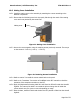
10.3 Cell Replacement from Cell Holder with Stand Alone Spring
10.3.1 At this point, two options are available depending on the manufacturing date of the
remote switch:
The remote switch was manufactured with an
individual spring unattached to the cell holder.
Accordingly, proceed with the following
instructions.
This newest version of the remote switch was
manufactured with a built-in spring
permanently attached to the cell holder.
Accordingly, proceed to section 10.4.
Figure 11: Spring Configuration
Spring
Spring