
Instruction Manual


Artex Products / ACR Electronics, Inc. 570-0023 Rev. G
Page 29 of 33
10.5 Mating Cover Installation
10.5.1 Install the mating cover to the assembly by matching the cutouts according to the
different components.
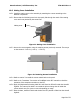
10.5.2 Ensure that the 26 AWG ground wire is properly fed through the notch of the mating
cover and is not pinched by the screw boss.
Figure 21: Mating Cover Installation
10.5.3 Secure the covers together using the retaining screws previously removed. The torque
on the screws is 2.0 Lb-in (+0 Lb-in, - 0.5 Lb-in).
Figure 22: Retaining Screws Installation
10.5.4 Refer to section 7 to install the remote switch back on the panel.
10.5.5 Refer to the Transmitter Test section of the ME406 series ELT manuals to check the
operation of the complete connection to the ELT.
10.5.6 Apply Cell Replacement Warning label 591-0036 from kit 455-0023 inside the aircraft’s
logbook. The intent of the label is to remind the pilot to change the cell inside the
remote switch every five years or sooner depending on usage.
10.5.7 Enter the date, installer’s initials and whether the ELT passed or failed into the aircraft
logbook.
Mating cover