
Instruction Manual

Artex Products / ACR Electronics, Inc. 570-0023 Rev. G
Page 7 of 33
List of Figures
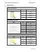
Figure 1: Wiring Diagram for Shielded Cable (Composite Aircraft) ........................................................ 11
Figure 2: Wiring Diagram for Unshielded Telephone Cable ................................................................... 11
Figure 3: Wiring Diagram for Shielded Cable (Metal Aircraft) ................................................................ 12
Figure 4: Wiring Diagram for Unshielded Telephone Cable (Metal Aircraft) ............................................ 12
Figure 5: Labels 591-0003 & 591-3029 ............................................................................................... 16
Figure 6: Panel Cutout Dimensions ..................................................................................................... 16
Figure 7: Harness to Remote Switch Connection ................................................................................. 18
Figure 8: Remote Switch Orientation .................................................................................................. 18
Figure 9: Remote switch wire tensile load release ............................................................................... 19
Figure 10: Module Interface to ELT Connection ................................................................................... 20
Figure 11: Spring Configuration .......................................................................................................... 22
Figure 12: Conical Spring ................................................................................................................... 23
Figure 13: Conical Spring Installation ................................................................................................. 23
Figure 14: Cell Holder Wires .............................................................................................................. 24
Figure 15: Ground Wire ..................................................................................................................... 25
Figure 16: Cell Installation ................................................................................................................. 26
Figure 17: Spring Installation ............................................................................................................. 26
Figure 18: Spring Fit .......................................................................................................................... 27
Figure 19: Cell Holder Wires .............................................................................................................. 27
Figure 20: Ground Wire ..................................................................................................................... 28
Figure 21: Mating Cover Installation ................................................................................................... 29
Figure 22: Retaining Screws Installation ............................................................................................. 29
Figure 23: 453-0023 Remote Switch ................................................................................................... 31
Figure 24: 453-1101 Module Interface ................................................................................................ 31