
Instruction Manual


Artex Products / ACR Electronics, Inc. 570-0023 Rev. G
Page 9 of 33
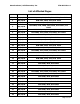
3. WIRING PIN OUT
The following information highlights the pin out of the remote switch and module interface.
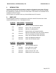
Remote Switch Back View
VIEW
PIN #
SIGNAL DESCRIPTION
PIN 2
2
Light
3
External On
4
Reset 1
5
Reset 2
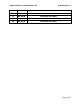
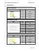
Module Interface Front View
VIEW
PIN #
SIGNAL DESCRIPTION
2
Light
5
G-Switch Loop
6
Reset 1
7
Ground
8
Horn Power
12
G-Switch Loop
13
Reset 2
14
External ON
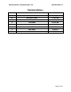
Module Interface Back View
VIEW
PIN #
SIGNAL DESCRIPTION
PIN 2
2
Light
3
External On
4
Reset 1
5
Reset 2