
User guide

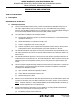


Table Of Contents
- Record of Revisions
- Service Bulletin List
- List of Effective Pages
- Table of Contents
- List of Figures
- Introduction
- Description and Operation
- Test and Fault Isolation
- 1. Inspection and Test Regulatory Requirements
- 2. Inspection and Test Procedures
- A. Checklist
- B. Preparation
- C. Coax Cable and Wiring Connections Inspection – Item 1
- D. Mounting Tray and Hardware Inspection – Item 2
- E. Battery Pack Inspection – Item 3
- F. G-Switch Functional Check – Item 4
- G. Performance Testing Setup
- H. 121.5 MHz Frequency Measurement – Item 5a
- I. Audio Modulation Check – Item 5b
- J. 121.5 MHz Power Output Measurement – Item 5c
- K. 406 MHz Frequency Measurement – Item 5d
- L. 406 MHz Power Output Measurement – Item 5e
- M. Current Draw Test – Item 5f
- N. Digital Message Verification – Item 5g
- O. ELT Reset Check – Item 5h
- P. Installed Transmitter Test – Item 6
- Q. Antenna Test – Item 7
- R. Inspection and Test Documentation – Item 8
- 3. Fault Isolation
- Removal
- Installation
- 1. Regulatory Requirements and Guidelines
- 2. Mounting Tray
- 3. Antenna
- 4. Remote Switch
- 5. Buzzer
- 6. Wiring
- A. General Considerations and Recommendations
- B. Remote Switch Harness Fabrication
- C. ELT D-Sub Plug Installation
- D. Cockpit Remote Switch 9-Pin Plug Installation
- E. Wiring Installation
- F. Antenna Connection
- G. Cockpit Remote Switch Power Connection
- H. Remote Switch Alternate Power Source
- I. Airframe Ground Connections
- J. Buzzer Connections
- K. Remote Switch Final Installation
- 7. ELT Installation
- 8. Battery Pack Installation
- 9. Helicopter Installations - Special Considerations
- Appendix A – ELT Registration
- Illustrated Parts List

ARTEX PRODUCTS / ACR ELECTRONICS, INC
DESCRIPTION, OPERATION, INSTALLATION AND MAINTENANCE MANUAL
ME406 (453-6603), ME406HM (453-6604)
25-62-30
Page 26 of 84
Jun 25/13
TASK 25-62-30-870-802
2. Operation
SUBTASK 25-62-30-870-001
A. Operational Overview
(1) See Figure 7 ELT Operational Flow Diagram.
Figure 7 ELT Operational Flow Diagram
(2) A primary feature of the ME406 Series ELT is its simplicity of operation. As long as the ELT is
connected to the remote switch harness ELT connector, such that pins 5 and 12 are jumpered
(G-switch loop), it will activate in the event of a crash.
NOTE
: Neither the cockpit remote switch or the ELT local switch can be positioned in such a
manner as to prevent automatic activation when the ELT is connected properly.
(3) ELT operation is designed to prevent human error and misuse in regards to automatic
activation. The ELT cannot be activated by dropping, rough handling or during shipping.
(4) When the ELT is activated, the presence of the emergency sweep tone and the flashing
cockpit remote switch panel LED indicates an active, normal functioning ELT. The cockpit
panel LED must immediately begin to flash continuously upon ELT activation.
(5) The ELT is considered to be either “ACTIVE” or “INACTIVE”. When “INACTIVE”, the ELT is in a
state of rest and performs no functions. Taking the ELT from the “INACTIVE” state to the
“ACTIVE” state requires a positive switch transition from either the cockpit remote switch, ELT
local switch, or G-switch.
ELT
“INACTIVE”
ELT “ACTIVE”
BUZZER “ON”
LED “ON”
ELT
SWITCH
“ON”
REMOTE
SWITCH
“ON”
G-SWITCH
“ON”
ELT OR
REMOTE SW
“RESET”
YES
YES
NO
NO
NO
YES
NO
YES