
User guide


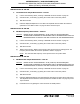


Table Of Contents
- Record of Revisions
- Service Bulletin List
- List of Effective Pages
- Table of Contents
- List of Figures
- Introduction
- Description and Operation
- Test and Fault Isolation
- 1. Inspection and Test Regulatory Requirements
- 2. Inspection and Test Procedures
- A. Checklist
- B. Preparation
- C. Coax Cable and Wiring Connections Inspection – Item 1
- D. Mounting Tray and Hardware Inspection – Item 2
- E. Battery Pack Inspection – Item 3
- F. G-Switch Functional Check – Item 4
- G. Performance Testing Setup
- H. 121.5 MHz Frequency Measurement – Item 5a
- I. Audio Modulation Check – Item 5b
- J. 121.5 MHz Power Output Measurement – Item 5c
- K. 406 MHz Frequency Measurement – Item 5d
- L. 406 MHz Power Output Measurement – Item 5e
- M. Current Draw Test – Item 5f
- N. Digital Message Verification – Item 5g
- O. ELT Reset Check – Item 5h
- P. Installed Transmitter Test – Item 6
- Q. Antenna Test – Item 7
- R. Inspection and Test Documentation – Item 8
- 3. Fault Isolation
- Removal
- Installation
- 1. Regulatory Requirements and Guidelines
- 2. Mounting Tray
- 3. Antenna
- 4. Remote Switch
- 5. Buzzer
- 6. Wiring
- A. General Considerations and Recommendations
- B. Remote Switch Harness Fabrication
- C. ELT D-Sub Plug Installation
- D. Cockpit Remote Switch 9-Pin Plug Installation
- E. Wiring Installation
- F. Antenna Connection
- G. Cockpit Remote Switch Power Connection
- H. Remote Switch Alternate Power Source
- I. Airframe Ground Connections
- J. Buzzer Connections
- K. Remote Switch Final Installation
- 7. ELT Installation
- 8. Battery Pack Installation
- 9. Helicopter Installations - Special Considerations
- Appendix A – ELT Registration
- Illustrated Parts List

ARTEX PRODUCTS / ACR ELECTRONICS, INC
DESCRIPTION, OPERATION, INSTALLATION AND MAINTENANCE MANUAL
ME406 (453-6603), ME406HM (453-6604)
25-62-30
Page 38 of 84
Jun 25/13
SUBTASK 25-62-30-750-008
M. Current Draw Test – Item 5f
CAUTION
: EXERCISE EXTREME CAUTION TO AVOID CAUSING A SHORT CIRCUIT CONDITION,
WHICH WILL BLOW THE FUSES IN THE BATTERY PACK. THIS TEST SHOULD ONLY BE
PERFORMED BY AN EXPERIENCED TECHNICIAN/MECHANIC.
CAUTION
: ALL “ON” STATE CURRENT MEASUREMENTS MUST BE MADE WITH THE RF OUTPUT
(I.E., ELT ANTENNA CONNECTOR) LOADED WITH 50 OHMS RATED FOR 5 WATTS.
EITHER A RESISTIVE LOAD OR EQUIPMENT WITH 50 OHM IMPEDANCE PADDED WITH
A 10 DB/5 WATT ATTENUATOR. REFER TO SUBTASK 25-62-30-750-002 ON PAGE 35.
CAUTION
: ACR ELECTRONICS DOES NOT RECOMMEND MEASURING THE 406 MHZ BURST,
WHICH DRAWS UP TO 5 AMPS OF CURRENT; HOWEVER, THE AMMETER USED TO
MEASURE THE STEADY STATE CURRENT OF THE 121.5 MHZ TRANSMISSION MUST BE
CAPABLE OF WITHSTANDING A 5 AMP CURRENT DRAW OR MUST HAVE THE READING
SCALE ADJUSTED ACCORDINGLY. KEEP IN MIND THE ELT TRANSMITS A 406 MHZ
BURST WHEN THE ELT IS RESET, IN ADDITION TO A 406 MHZ BURST
APPROXIMATELY EVERY 50 SECONDS.
(1) Verify the ELT control switch is in the “ARM” position.
Separate the battery pack from the ELT. See SUBTASK 25-62-30-050-001 on page 46
(2) Install test fixture 500-0057 in the power circuit. See Figure 9 Current Draw Test Setup.
Figure 9 Current Draw Test Setup
(3) Connect the ammeter and set it for the lowest possible scale.
(4) Read the current draw on the ammeter. Measured current must be £ 2 µA (micro-amps).
TEST FIXTURE
500-0057
CONNECT ELT FLEX
CABLE HERE
CONNECT TEST FIXTURE
TO BATTERY PACK PLUG
+
A
—