PRODUCT SUPPORT MANUAL RCL-100D // Remote Control Searchlight System Model No.: RCL-100D Product No.: 1930.3, 1931.3 Y1-03-0138 Rev. V ACR Electronics, Inc., // 5757 Ravenswood Road // Fort Lauderdale // FL // 33312-6645 Y1-03-0138U T: +1 (954) 981-3333 // F: +1(954) 983-5087 // www.acrartex.
Table of Contents SECTION 1 - FOREWORD ___________________________ 3 SECTION 2 - GENERAL _____________________________ 4 SECTION 3 - SEARCHLIGHT _________________________ 4 SECTION 4 - REMOTE CONTROL SYSTEM ______________ 5 SECTION 5 - URP-102 POINT PAD™___________________ 5 SECTION 6 - URC-102 MASTER CONTROLLER __________ 10 APPENDIX A - RCL-100D SPECIFICATIONS _____________ 16 APPENDIX B - USER REPLACEABLE PARTS _____________ 17 APPENDIX C - BULB REPLACEMENT PROCEDURE _______ 18 APPENDIX D - PRODUCT COMP
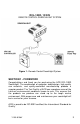
RCL-100D, 12/24V REMOTE CONTROL SEARCHLIGHT SYSTEM SEARCHLIGHT Figure 1 - Remote Control Searchlight System SECTION 1 - FOREWORD Congratulations and thank you for purchasing the ACR RCL-100D Searchlight. The combination of computer aided design, high quality raw materials, and quality-controlled manufacturing produce a superior product. The Test Facility at ACR can reproduce some of the harshest environmental conditions known to man.
SECTION 2 - GENERAL The RCL-100D was specially designed for mariners who require a high intensity remote controlled searchlight that can stand up to the tough marine environment. The RCL-100D Searchlight System contains a narrow beam searchlight that produces 200,000 peak candle power by combining two 55W halogen lamps with our unique optical quality parabolic reflectors.
NOTE: The Searchlight should be left uncovered if the XRCiZ feature is enabled. SECTION 4 - REMOTE CONTROL SYSTEM The Remote Control System consists of the URC-102 Master Controller and the URP-102 Point Pad™. This system is compatible with 12 VDC and 24 VDC systems without modification. The Remote Control System may be used with 12 V or 24 V Searchlights, ONLY THE LAMPS IN THE LIGHT HEAD ASSEMBLY MUST BE CHANGED TO MATCH THE VOLTAGE RATING.
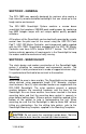
standard "F" type television connectors. The connector on the back of the Point Pad™ is located in the center of the panel for ease of installation. After the coax cable has been routed and the “F” connectors attached to the coax cable, simply screw the “F” connectors to the Master Controller and the Point Pad™. The cable and connectors are available either through ACR Electronics, your local Radio Shack or other sources of electronic hardware.
URC-102 Master Controller Unit URC-102 Master Controller Unit RG-59 Coaxial Cable Fuse URP-102 Point Pad Power Source RG-59 Coaxial Cable Fuse “T” Conn.
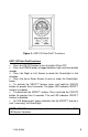
Figure 3 - URP-102 Point Pad™ Functions URP-102 Point Pad Functions Press the ON/OFF button to turn the lights ON or OFF. Press the SPEED button to toggle between High and Low rotation speeds. Press the Right or Left Arrows to rotate the Searchlight in that direction. Press the Up or Down Arrows to raise or lower the Searchlightbeam. To activate the XRCiZ™ feature, press and hold the ON/OFF button for greater than 5 seconds. The green LED indicates XRCiZ™ feature is enabled.
Figure 4 - URP-102 Point Pad™ Surface Mount Case Figure 5 - URP-102 Point Pad™ Flush Mount Case Y1-03-0138V 9
Figure 6 - URP-102 Point Pad™ Surface Mount Case with gasket and Flush Mount Case with gasket SECTION 6 - URC-102 MASTER CONTROLLER Mounting The Master Controller can be mounted in any position near the Searchlight that is protected from the weather. Check in advance that the coax cable from the Point Pad™ and the wiring harness from the Searchlight can be routed to this location. Mount the Master controller with the wires and coax facing down. Use an appropriate fastener for your mounting location.
Master Controller Wire Orange Blue Yellow Green Red White Black Brown Searchlight Cable Wire Power Source Lead +12 VDC or +24 VDC** Ground Yellow Green Red White Black Brown Function Power Ground Lamp Power Lamp Ground Up Down Right Left Table 1 WARNING: This wire MUST be fused with a 15 amp fuse in the Master Controller's in-line fuse-holder. Wiring to Searchlight The RCL-100 Searchlight is supplied with a 15 foot integral wire harness.
NOTE: As per the wiring scheme, the ORANGE wire is connected to the Positive terminal and the BLUE wire is connected to the Negative terminal of the power source. CAUTION: Observe polarities when attaching wires! Maximum Cable Length Wire Size #8 AWG #10 AWG #12 AWG 12v System 25 ft. 15 ft. 10 ft. 24v System 100 ft. 60 ft. 40 ft. Table 2 Function The URC-102 Master Controller is designed to perform up to six different duties on searchlights, winches, and other electrical devices.
To deactivate the XRCiZ™ feature, press and hold the Point Pad™ ON/OFF button for greater than 5 seconds. The Red LED on the URC-102 Point Pad™ indicates that the XRCiZ™ feature is disabled. NOTE: LED feedback is not available when using RCL-100 or URC101 Point Pads™. NOTE: The Searchlight should not be covered while the XRCiZ™ feature is enabled. The URC-102 Master Controller provides optimum voltage to ensure the brightest searchlight performance and long bulb life.
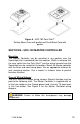
Power Source Fuse Spotlight 12 VDC or 24 VDC Master Controller in-line 15 amp fuse Ground Blue Orange Master Yellow Lamp Power Green Lamp Ground Red Spot Up White Spot Down Brown Spot Left Black Spot Right 75 ohm TV Coaxial Cable “T” Connector or Optional 75 Ohm Splitter for Multiple RCL-100 Point Pads Other RCL-100 Point Pads 75 ohm TV Coaxial Cable RCL-100 Point Pad Note: Wiring must be in accordance with this diagram. Improper wiring will damage components.
Figure 8 - URC-102 Master Controller Y1-03-0138V 15
APPENDIX A - RCL-100D SPECIFICATIONS (with URC-102 Controller) Specification 12V Unit 24V Unit 4in (10.16cm) X 4in (10.16cm) X 2.75in (6.99cm) 2.75in (6.99cm) Rated voltage (Volt) 12- 16 VDC 24- 31 VDC Rated current (A) 10 5 55W halogen 70W halogen Lamp X 2 Lamp X2 Mirror diameter Applicable lamp (base –G6.35) (base –G6.
APPENDIX B - USER REPLACEABLE PARTS ACR/RCL-100D Figure 9 - Searchlight User Replaceable Parts Item Number 1 2 3A 3B 3C 4 5 6 7 8A 8B 9 10 11 Y1-03-0138U Description Quantity Front Glass Front Frame Window Weather Strip Screw M4x18 Washer M408 Gasket of front frame 10 cm reflector Protection Cover O-Ring #594 55W quartz halogen bulb (12V) 55W quartz halogen bulb (24V) Shoulder Washer Base Housing Head Housing 1 1 1 2 2 1 2 1 1 2 2 4 1 1 ACR Part Number HRMK 1300 HRMK 2101 HRMK 1201 HRMK 1600 HRMK 930
APPENDIX C - BULB REPLACEMENT PROCEDURE Two 55W, quartz-halogen bulbs are provided with your RCL-100D. If they should need replacement, they can be ordered through an ACR dealer or through ACR Electronics. The part numbers are P/N 6001 for 12V units and P/N 6003 for 24V units. CAUTION: Failure to follow replacement instructions carefully can result in damage to bulb and/or light. All part sales are final. To replace the lamps: 1. Disconnect unit from power source and allow bulbs to cool. 2.
APPENDIX D - PRODUCT COMPONENTS Product No. 1930.
APPENDIX E - ACCESSORY COMPONENTS Product No. 1927.3 - URC-102 Master Controller Installation Kit includes: Description Master Controller, URC-102 Quantity 1 Connector, "In-Line" Instruction Controller Sheet, Master ACR Part Number A3-06-2231 8 A1-03-0222 1 Y1-06-0178 Product No. 1928.
Product No. 9282.
APPENDIX F - WARRANTY, NOTICES Limited Warranty This product is warranted against factory defects in material and workmanship for a period of 1 (one) year* from date of purchase or receipt as a gift. During the warranty period ACR Electronics, Inc. will repair or, at its option, replace the unit at no cost to you for labor, materials and return transportation from ACR. For further assistance, please contact our Technical Service Department at ACR Electronics, Inc.
EC DECLARATION OF CONFORMITY ACR Electronics, Inc. hereby declares that the following product is in conformity with Directive 2004/108/EC of the European Parliament and of the Council of 15 December 2004 on Electromagnetic Compatibility (EMC Directive).