PRODUCT SUPPORT MANUAL GLOBALFIX™ iPRO 406 MHz GPS EPIRB // Model No.: RLB-36 Product No.: 2846.0, 2848.0 Y1-03-0233 Rev. J ACR Electronics, Inc. // 5757 Ravenswood Road // Fort Lauderdale // FL // 33312-6645 Tel: +1 (954) 981-3333 // Fax: +1 (954) 983-5087 // www.acrartex.
CAUTION: Before proceeding to install, test or use your new ACR Electronics’ product, please read this Product Support Manual in its entirety. If you have questions regarding the contents of the manual, please contact our Technical Service Department at ACR Electronics, Inc., Telephone +1 (954) 981- 3333. Please be ready to provide the technician with the page number you wish to discuss.
Table of Contents STEP ONE - REGISTERING YOUR BEACON ___________________________________ 2 STEP TWO - HOW THE BEACON WORKS ____________________________________ 6 STEP THREE - INSTALLING THE BEACON ___________________________________ 16 STEP FOUR - MAINTAINING THE BEACON __________________________________ 21 APPENDIX A - USING AND TESTING THE GPS SYSTEMS ________________________ 27 APPENDIX B - USER INTERFACE: SPECIAL ICONS ______________________________ 29 APPENDIX C - USER INTERFACE: DIGITAL DISPLAY DURING
STEP ONE - REGISTERING YOUR BEACON 1. Why is registration important? As the owner of this 406 MHz beacon, it is mandatory that you register it with the EPIRB national authority of your country: It is the law. Please note that all 406 MHz beacons are required to have their registration updated every two years by the owner. Your unique ID code programmed inside each EPIRB is transmitted to Search and Rescue (SAR).
2. What country should I register in? Register your beacon with the EPIRB national authority of the country for which the beacon was programmed, typically the country where purchased, regardless of where you do your boating. The beacon must be reprogrammed if you, as the owner, move or the vessel sails under the flag of a different country than the one for which the beacon was previously programmed.
Registration outside of the United States In countries other than the United States, 406 MHz beacons are registered with that country’s national authority at the time of purchase. The sales agent should have assisted you in filling out the forms and sending them to the country’s national authority. Alternatively, many countries allow online registration in the International 406 MHz Beacon Registration Database (IBRD) at www.406registration.com.
STEP TWO - HOW THE BEACON WORKS 1. How your beacon brings help 406 MHz beacons are a type of portable emergency equipment that transmits a distress signal to search and rescue (SAR) organizations. The purpose of these beacons is to aid SAR teams in tracking and locating ships or individuals in jeopardy as rapidly as possible. The 406 MHz frequency is a worldwide dedicated emergency frequency that is detected by a special system of satellites called the CospasSarsat system.
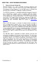
2. Anatomy of your beacon NOTE: When unpacking your beacon, it is recommended that you save the original packaging for re-use when shipping the beacon for battery replacement in the future. // Activation switch with Witness Tab The activation switch embodies a special, patented method of activating a beacon. Refer to a subsequent section of this manual for how to activate the beacon. // External GPS interface The external GPS interface serves as the connection to the ship’s GPS system.
Strobes Antenna Top View GPS Interface Activation/Test Switch Green LED Red LED Digital Display Screen Internal GPS Receiver Switch Positions TEST Position OFF/READY Position Y1-03-0233 Rev.
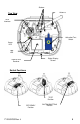
Category 1 – SeaShelter™3 Bracket HydroFix™ Hydrostatic Release Unit (HRU) Spring Release knob Ejector spring Antenna hook GPS Interface Cable Front cover hook (detent) Category 2 – LowPro™3 Bracket Water Sensor Deactivation Magnet Antenna hook GPS Interface Stowage Port Front Cover Release Tabs Release Latch Y1-03-0233 Rev.
3. Digital Display The digital display in the beacon is used as a secondary visual aid, supporting the green/red LED and the audio tone, which indicate the status of the beacon during testing and during emergency operation. The messages on the digital display typically appear as one or two words at a time, until the entire message has been displayed. When the beacon is activated, the display will show the message EPIRB ON.
4. Activating your beacon WARNING: This transmitter is authorized for use only during situations of grave and imminent danger. Deliberate misuse may incur a severe penalty. Overview Category I beacons are designed to be automatically deployed and activated in the event of a sinking vessel. The beacon may also be hand held on the deck of vessels, or floated in water and attached to a raft or life vest with the lanyard provided. Category II beacons are designed to be manually deployed from the bracket.
Category I beacons-Automatic deployment and activation If the vessel sinks, the HydroFix™ HRU frees the beacon from the bracket, allowing it to float to the surface. Built-in sensors detect that the beacon is no longer in its bracket and when continuity is created by water between two of the top cap screws, an activation circuit is completed. NOTE: Transmission of the 121.5 MHz and 406 MHz signals will not occur until 100 seconds after activation.
Category I and II Beacons-Manual deployment and activation Both Category I and II beacons can be manually deployed by removing the beacon from the bracket. Once removed, the beacon can be activated by placing it in water OR by lifting the Activation Switch to a vertical position, sliding it toward the antenna and pushing down to the opposite side of the beacon. Activating the beacon in this manner breaks off the Activation Witness Tab and allows the switch to properly seat, showing the “ ▌ “ symbol (ON).
TIPS FOR OPTIMUM DEPLOYMENT OF AN ACTIVATED BEACON: When activating and deploying your beacon in an emergency, DO NOT: // Hold or clutch the beacon or antenna // Operate the beacon while hand held, if at all possible // Turn the beacon off for any reason, including to save power // Activate the beacon if you have any other means of self rescue // Operate the beacon inside a life raft or under any other canopy or cover // Tether the beacon to the bracket or vessel When activating and deploying your beacon in
// // // // Precautions to prevent false alarms Do not mount or transport the beacon within 4.6ft/1.4m of a magnetic source. Do not store the beacon outside of its bracket if it can get wet. Do not mount the EPIRB backwards in its bracket (lanyard roll must face in). Do not clean the beacon with a water hose and brush while out of its bracket. Reporting Should there be, for any reason, an inadvertent activation or false alarm, it must be reported to the nearest search and rescue authorities.
STEP THREE - INSTALLING THE BEACON 1. Marking battery and Hydrostatic Release Unit expiration dates NOTE: It is the beacon owner’s responsibility to record the expiration dates for both the beacon battery and the HydroFix™ hydrostatic release unit. This information must appear on the product itself. The left side of the battery housing indicates the battery expiry date. Space is provided for the beacon owner to mark the date the beacon was placed into service.
CAUTION: Category I brackets must be mounted free from obstruction to allow the beacon to automatically float free from the vessel in case of sinking. The SeaShelter3™ can be mounted on a vertical surface with the beacon antenna pointing skyward or a horizontal surface with the beacon face up. Avoid mounting locations that subject the bracket to breaking waves. Avoid structures like dodgers or cabin tops that could trap the beacon upon deployment.
CAUTION: Keep this beacon a safe distance away from all magnetic sources. Magnet safe distance is 4.6ft. or 1.4m, including the distance from stereo speakers. 3. Category I bracket The SeaShelter3™ Category I bracket has five pre-drilled screw holes to use for securing the bracket to a flat surface. Remove the SeaShelter 3™ lid by turning the spring loaded knob on the lid 1/4 turn counterclockwise and pull. The lid will lift away from the top of the base and disengage at the bottom of the base.
4. Category II bracket Category II brackets are designed to hold the beacon securely in place. The beacon must be manually deployed. The bracket can be mounted on a vertical flat surface with beacon antenna up or on a horizontal flat surface facing skyward. This location must be easily accessible in order to manually deploy the beacon or to perform the required maintenance and functionality tests. Typical locations include near the helm station or just inside the companionway door.
5. Installing the optical interface to an external GPS receiver The beacon is fitted with an optical interface to connect with an external Global Positioning System (GPS) receiver that will determine the latitude and longitude of its position. The black lead wire with white stripes should be connected to the output of the external GPS receiver positive transmitter pin. The black wire should be connected to the negative pin.
STEP FOUR - MAINTAINING THE BEACON 1.
Always refer battery replacement and any other beacon service to a factory authorized Service Center. Find a Center near you at http://www.acrartex.com. Battery replacement includes servicing the beacon by replacing all o-rings, testing the water seal and the electrical properties and doing a full functional test on the unit. NOTE: There are no user serviceable items inside the beacon. Do not open the beacon except to disable (in case of faulty or accidental activation).
6. Changing ownership or contact information As the owner of the beacon, it is your responsibility to advise the national authority of any change in the information on the registration form. If you are transferring the beacon to a new owner, you are required to inform the national authority. You can do this by using their online database or by letter, fax or telephone and informing the authority of the name and address of the new owner.
To remove the expired HRU When opening the SeaShelter3™ lid, note that the beacon is installed with the lanyard face in. Pull the beacon with steady pressure from the bracket. Do not get beacon wet while out of bracket. The HRU has a keying feature that locks it to the bracket. If you view the HRU rod as the center of a clock, a properly installed HRU will rest at the 7 o’clock position, as shown in the picture above. WARNING: The HRU holds down an ejection spring.
9. Servicing the LowPro3™ To remove a beacon from the Category II bracket, lift the latch and release the pressure from the beacon. The beacon will now be able to slide upwards out of the bracket. ™ It is not anticipated that the LowPro 3 cleaning or, rarely, replacement. will require servicing other than Brackets are a key part of the overall beacon system. They hold a beacon ready for deployment while preventing false alarms.
11. Extended GPS test The beacon may be tested for GPS functionality, however, this may only be done once in the five-year lifetime of the battery due to the significant drain on the battery. This test is not necessary at any time in the life of the beacon, but is made available in the event that the beacon owner wishes to verify internal GPS engine viability. An extended GPS test may be invoked by holding the switch in test position for 10 seconds after Self-Test completes.
APPENDIX A - USING AND TESTING THE GPS SYSTEMS 1. How the external GPS interface works The beacon is fitted with an optical interface to connect with an external Global Positioning System (GPS) receiver that will determine the latitude and longitude of its position. This data is transmitted to the emergency system. When the beacon is coupled to a working external GPS receiver, it immediately begins downloading data.
This bypasses the normal, programmed, waiting time of 20 minutes for the automatic update of GPS position data. If the new GPS position is acquired, the coordinates will be displayed after the beacon has completed the Self-Test. If no valid GPS position data is available, the beacon will keep the previously stored GPS position data for up to 4 hours. In this case, call ACR Customer Service at +1 (954) 981-3333 for instructions on how to reset the beacon with the default message.
7. Compatible GPS receivers External GPS interface requirements: In order to be compatible with the GlobalFix™ iPRO, an external GPS receiver must provide location information according to the following requirements: // // // // NMEA 0183, Version 1.5 or higher Baud rate: 4800 Talker device identifier: GP (GPS Receiver) Sentence format: GGA (GPS Fix Data) For more information regarding external GPS device compatibility, please visit the ACR website at www.acrartex.com.
APPENDIX C - USER INTERFACE: DIGITAL DISPLAY DURING OPERATION The following chart describes the audio-visual feedback the beacon provides during activation. The messages on the digital display typically appear as one or two words at a time, until the entire message has been displayed.
121.5 ON G R The system reports that the 121.5 MHz homing signal is on. Search and Rescue (SAR) personnel use this frequency when arriving close to the scene. If this message is accompanied by a green LED flash, the GPS coordinates have been sent. If accompanied by a red LED flash, the GPS coordinates have not been sent. NOTE: If GPS coordinates were not sent, the system will continue to attempt to acquire the data and add it to the 406 MHz distress signal when available.
LEAVE G EPIRB ON UNTIL RES Q R The system reminds you that leaving the beacon on continuously gives the best assurance of being rescued. SAR groups need the ongoing transmissions from the beacon to most effectively find you. If this message is accompanied by a green LED flash, the GPS coordinates have been sent. If accompanied by a red LED flash, the GPS coordinates have not been sent.
APPENDIX D - USER INTERFACE: DIGITAL DISPLAY DURING SELF-TEST The following chart describes the display and audio-visual feedback the beacon provides during Self-Test. The messages on the digital display typically appear as one or two words at a time, until the entire message has been displayed. GlobalFix™ iPRO Display, LED/ Audio Signaling and Description of Operation Beacon Self-Test has been initiated, and the ACR Electronics’ Welcome Page appears. Next, the product name page appears.
406 RF TEST √ G beep The fourth test checks for 406 MHz signal strength/RF power. If power is adequate the system passes. 406 RF TEST R beep beep The fourth test checks for 406 MHz signal strength/RF power. If power is not adequate the system fails. GPS beep TEST √ G The fifth test checks GPS engine readiness. If the GPS is ready the beacon passes. GPS TEST R beep beep The fifth test checks GPS engine readiness. If the GPS is not ready the beacon fails.
NO NMEA GPS DATA This message appears if Self-Test has passed. The display indicates that the external GPS did not update its coordinates during Self-Test. NOTE: If external GPS data cannot be acquired, typically due to the external GPS not having achieved a good fix, it does not affect the pass status of Self-Test. Self-Test requires GPS engine readiness but does not require that the GPS obtain coordinates.
APPENDIX E - USER INTERFACE: DIGITAL DISPLAY DURING EXTENDED GPS TEST The following chart describes the display and audio-visual feedback the beacon provides during extended GPS Test. The messages on the digital display typically appear as one or two words at a time, until the entire message has been displayed. GlobalFix™ iPRO display, LED/ Audio Signaling and Description of Operation LONG GPS DATA TEST START The system informs you that the extended GPS test has initiated.
APPENDIX F- USER INTERFACE: LANGUAGE TRANSLATIONS The RLB-36 user interface is available in five languages: English, French, Italian, Spanish and German. The following table provides the digital display phrases that appear on the screen. Please note that all language translations utilize simple terms and abbreviations for the purpose of speed and readability of messages. English phrases EPIRB ON GPS ON GIVE CLEAR VIEW TO SKY DO NOT HOLD AERIAL* 406 SENT GPS SENT 121.
APPENDIX G - THE COSPAS-SARSAT SYSTEM 1. General overview EPIRBs transmit to the satellite portion of the Cospas-Sarsat system. Cospas-Sarast satellites are an international system that utilizes Russian Federation and United States’ low altitude, near-polar orbiting satellites (LEOSAR). These satellites assist in detecting and locating activated 406 MHz satellite beacons. Cospas-Sarsat satellites receive distress signals from EPIRBs transmitting on the frequency of 406 MHz.
APPENDIX H - TECHNICAL SPECIFICATIONS Beacon size (without antenna) Display size Beacon weight Beacon material Color Waterproof GENERAL/ ENVIRONMENTAL 17.7 H X 10.67 W X 9.09 D cm (6.97 X 4.2 X 3.58 in) 2.54 cm (1.0 in) diagonal 581 g (20.
APPENDIX I - WARRANTY, NOTICES 1. Limited Warranty This product is warranted against factory defects in material and workmanship for a period of 1 (one) year* from date of purchase or receipt as a gift. During the warranty period ACR Electronics, Inc. will repair or, at its option, replace the unit at no cost to you for labor, materials and return transportation from ACR. For further assistance, please contact our Technical Service Department at ACR Electronics, Inc.
EC DECLARATION OF CONFORMITY ACR Electronics hereby declares that the following product is in conformity with Council Directive 96/98/EC of 20 December 1996 on Marine Equipment (MED) last amended by Commission Directive 2011/75/EU of 2 September 2011, and has been type examined as described in this Declaration.
INTERNATIONAL MARITIME ORGANIZATION SHORE BASED MAINTENANCE The Maritime Safety Committee approved guidelines for shore-based maintenance (SBM) of satellite EPIRBs, for the purpose of establishing standardized procedures and minimum levels of service for the testing and maintenance of satellite EPIRBs to ensure maximum reliability whilst minimizing the risk of false distress alerts. (IMO MSC/Circ.