OWNER_____________________________ VESSEL_____________________________ RADIO CALL SIGN_____________________ 0
CAUTION: Before proceeding to install, test or use your new ACR Electronics’ product, please read this Product Support Manual in its entirety. If you have questions regarding the contents of the manual, please contact our Technical Service Department at ACR Electronics, Inc., Telephone +1 (954) 983- 3333. Please be ready to provide the technician with the page number you wish to discuss.
FOREWORD Congratulations and thank you for purchasing the ACR Memory capsule. The combination of superior design, high quality raw materials and quality controlled manufacturing produce a product that will perform for years to come. The test facility at ACR can reproduce some of the harshest environmental conditions known to man. This assures that the products we produce can stand up to the rigors found in a marine environment.
SECTION 1 - REGISTRATION OF 406 MHZ MEMORY CAPSULES 1.1 Why is registration important? As the owner of this 406 MHz beacon, it is mandatory that you register it with the EPIRB national authority of your country: It is the law. Please note that all 406 MHz beacons are required to have their registration updated every two years by the owner.
1.2 What country should I register in? Register your beacon with the EPIRB national authority of the country for which the beacon was programmed, typically the country where purchased, regardless of where you do your boating. The beacon must be reprogrammed if you, as the owner, move or the boat sails under a different country than the one for which the beacon was previously programmed.
1.5 Change of Ownership or Contact Information It is the owner’s responsibility to advise the national authority of any change in the information on the registration form. If the current owner is transferring the memory capsule to a new owner, the current owner is required to inform the National Authority by letter, fax or telephone, of the name and address of the new owner.
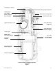
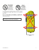
SeaShelter2™ Bracket Memory Capsule Antenna Warning Plate (not shown) Data Transfer Junction Box Memory Capsule Ejector Spring Data Transfer Cable Hydrostatic Release Unit Cutter Mechanism (Cable Slot) Cutter Mechanism (Activation Trigger) Strobe Light Water Sensor Deactivation Magnet Cat 5 Cable (Located behind bracket shield) Electronic Housing Data Transfer into Memory Capsule Battery Compartment Float Free Memory Capsule Components Front view Figure 1 Y1-03-0199 Rev.
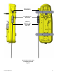
Data Transfer Junction Box RJ-45 Waterproof Connection PoE Cat 5 Ethernet cable from S-VDR Main Unit Side and Back view of Float Free Memory Capsule Figure 2 Y1-03-0199 Rev.
SECTION 3 - FALSE ALARMS 3.1 Prevention of False Alarms Your memory capsule can be activated by two different methods. 1. 2. When the memory capsule is out of its bracket and in the water, the unit is transmitting. When the switch is moved to the ON position, in or out of the bracket, the unit is transmitting. There are a few precautions that should be taken to prevent false alarms. Do not transport memory capsule within 1 meter (3.3ft) of a magnetic source.
The memory capsule should be mounted securely to a vertical or horizontal flat surface where there are no overhead obstructions. The use of #10 stainless steel hardware is recommended. There is no need to open the Sea Shelter or remove the SVDR during mounting. Note: The Sea Shelter has two mounting brackets for attachment to a flat surface (see Figure 3) Mounting hole locations Figure 3 Y1-03-0199 Rev.
4.2 Assembling your Float Free Memory Capsule (To remove all components, reverse these directions at step 5). NOTE: HRU and cutter assembly replacement can be performed more easily by removing the Sea Shelter from the bulkhead first. This can be done by removing the screws holding the mounting brackets to the bulkhead. 1. HRU and warning plate installation A) Push the release spring back against the bracket aligning the holes on the spring with the holes in the back of the bracket.
2. Cutter Mechanism Installation Cutter Mechanism Installation (Figure 6) Flex Cable Slot Release Pin Release Arm A) Insert the flex cable cutter mechanism into place. B) Position the cutter with the release arm extending across the ejector spring and the slot for the flex cable positioned at the top. C) Simply push the cutter into the slot until the teeth connect and lock the mechanism into place. Try to pull it back out to make sure the device is locked in securely.
3. ZIF Connection and Data Transfer Cable Installation Data is stored in the memory capsule using the data transfer cable which connects to the junction box on the bracket, runs thru the cutter mechanism and attaches to the left side of the memory capsule. This cable is connected to both the junction box and the memory capsule using ZIF (Zero Insertion Force) connectors. NOTE: ZIF connectors are fragile. To avoid breaking the connectors, touch them carefully.
Align the side window cap holes with the memory capsule or bracket and using a phillips head screwdriver, fasten the window cap in place with the provided screws. Window Cap Installation Figure 8 4.2.5 Data Transfer Cable Alignment Data Transfer Cable Alignment Figure 9 The data transfer cable connects the memory capsule to the bracket which in turn connects to the PoE and S-VDR. The flex data cable comes with two flex connectors on either end accompanied by protective window caps.
Data Transfer Cable in Cutter Figure 10 The installation step is placing the data transfer cable inside the cutter mechanism. Remove the top screw from the flex cable slot and open the white door (see Figure 10). Slide the data transfer cable along the side of the cutter mechanism and into the slot as shown above. Close the flex cable slot door and secure shut with by replacing the top screw. Final Installation Steps: Now the memory capsule is armed and ready for service.
Cutter Mechanism HRU Expiration Date Labels Figure 11 Memory Capsule SECTION 5 - OPERATION 5.1 General The memory capsule is designed to be automatically deployed and activated. The memory capsule is designed to operate best while floating in water. Hand held operation should be avoided when possible. Do not operate inside a life raft or under any similar cover or canopy. Changes in the laws governing memory capsules have mandated that the memory capsule be armed at all times.
5.3 Manual Deployment and Activation The memory capsule can be manually activated by lifting the thumb switch to a vertical position, sliding it towards the antenna and pushing back down to the opposite side of the memory capsule. Activating the memory capsule in this manner breaks off the ―Activation Indicator Plastic Pin‖ and allows the switch to properly seat, show the ―I‖ symbol (ON). Memory Capsule Instruction Label Figure 12 5.
The memory capsule can be tested in or out of the release bracket. The sequence of tests is: 1. Check Data Integrity ........................................ Beep and lights up red LED if passed ............................................................................. Stop if failed 2. Check 406 MHz Synthesizer ........................... Beep and lights up red LED if passed ............................................................................. Stop if failed 3. Check RF Power/Battery ...........
SECTION 6 - CARE AND MAINTENANCE At least every ninety days, the mounting bracket and float free memory capsule should be inspected for deterioration and/or buildup that may affect the function of the memory capsule or automatic release. Also carefully inspect the memory capsule case for any visible cracks. Cracks may admit moisture, which could falsely activate the memory capsule or otherwise cause a malfunction.
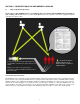
SECTION 7 - THE SEARCH AND RESCUE SYSTEM 7.1 General Overview Memory capsule's provides distress alerting via radio transmission on 406 MHz to satellites of the Cospas-Sarsat network. ACR's Float Free 406 Memory Capsule can also transmit a distress alert to the GEOSAR network that includes GPS latitude and longitude coordinates that are inputted through an I/R Interface that connects to the data output of a GPS Receiver.
Figure 13- Satellite coverage Figure 14- GEOSAR satellite orbits Figure 15- GPS satellite orbits Y1-03-0199 Rev.
SECTION 8 - AUTHORIZATIONS 8.1 Approvals The memory capsule meets the requirements of Federal Communications Commission (FCC) Part 80; and GMDSS. Applicable Documents: RTCM Cospas-Sarsat FCC Standard for 406 MHz Satellite EPIRBs Document C/S T.001 Oct. 04, C/S T.007, Oct. 04 Part 80.1101(C) (s): EPIRB Part 80, subpart W: GMDSS For complete type approval information, please refer to our website at www.acrelectronics.com. 8.2 Characteristics The memory capsule is a floatable, battery operated unit.
Antenna Frequency Polarization VSWR GPS Antenna Xenon Strobe Light Color Output Power Flash Rate General/Environmental Battery Life Operating Replacement Interval Operating Temperature Range Storage Temperature Range Size (EPIRB less Antenna) Antenna Height EPIRB Material Color Weight (complete assembly) Waterproof 8.5 Accessories Mounting Case Construction Size Release System 406 & 121.500 MHz Vertical Less than 1.5/1 12 Channel Parallel Receiver White 0.
SECTION 9- WARRANTY 9.1 Limited Warranty This product is warranted against factory defects in material and workmanship for a period of 1 (one) year* from date of purchase or receipt as a gift. During the warranty period ACR Electronics, Inc. will repair or, at its option, replace the unit at no cost to you for labor, materials and return transportation from ACR. For further assistance, please contact our Technical Service Department at ACR Electronics, Inc.
EC DECLARATION OF CONFORMITY ACR Electronics, Inc. hereby declares that the following product is in conformity with Council Directive 96/98/EC of 20 December 1996 on Marine Equipment (MED) as amended by Commission Directive 2002/75/EC of 2 September 2002, and has been type examined as described in this Declaration.
INTERNATIONAL MARITIME ORGANIZATION SHORE BASED MAINTENANCE The Maritime Safety Committee approved guidelines for shore-based maintenance (SBM) of satellite EPIRBs, for the purpose of establishing standardized procedures and minimum levels of service for the testing and maintenance of satellite EPIRBs to ensure maximum reliability whilst minimizing the risk of false distress alerts. (IMO MSC/Circ.