Instruction Manual.
Document Index. 6 Servicing & Maintenance Instructions 1 Installation Requirements 7 Spare Parts 1.1 Introduction 1.2 General 1.3 Electrical Supply 1.3.1 Electronic Controller 1.3.2 SmartElec2 Controller 1.4 Location 1.5 Clearance Distance 1.6 Health and Safety 1.7 Standards 7.1 General 7.2 AC-ACR-PANEL Controller 7.3 SmartElec2 Controller 7.4 Heating mediums 8 Fault Finding Guide 8.1 General 8.2 Electrical Heated 8.3 Electronic Controller 8.4 Optional SmartElec2 Controller 8.4.1 Fault Code chart 8.4.
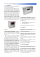
General Information 1.1 Introduction This instruction manual describes the Airbloc ACR Recessed range of air curtains. 0 F1 Models range from 1000mm to 2000mm in length, in both Standard and High capacity and are available in either Electrically heated, Ambient or LPHW. They are designed for discreet positioning in a suspended ceiling or bulkhead in the doorways of retail or commercial premises. Optional case for doorways with restricted space and no suspended ceiling/bulkhead are available.
BMS control, time switches, room thermostats and door interlocks can be installed at the discretion and responsibility of the installer. below. The clearance allows for cable entry and prevents combustible surfaces overheating. All units must be wired in accordance with I.E.E regulations for the Electrical Equipment of Buildings and the installer should ensure that a suitable isolating switch is connected in the mains supply. The minimum mounting height (floor to grille) is 1.8m.
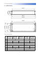
2. Dimensions. 2.
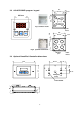
87.0 2.2 AC-ACR-PANEL program keypad 60.3crs 43.5 60.3crs 13.35 Fig.3. Surface mount Cable Entries 75.0 7.35 SELECT 7.35 60.3crs 60.3crs Fig.4. optional flush mount Earthing point Cable Entries 2.
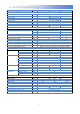
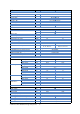
3. Technical Specification. 3.1 (Single Phase only) ACR100SE6-1PH ACR150SE6-1PH ACR200SE9-1PH 1.2 3.0 1.5 Electric heated 2.0 General Data Maximum height Door width Heat medium Heat setting Fan type / dia Fan settings Switching type Weight Electrical Data Supply voltage Total load M M kW kg Air velocity Delta T Noise level @ 1M Free field 4.5 / 9 49.
3.2 ACR100SE9 ACR150SE12 ACR200SE18 General Data Maximum height Door width Heat medium Heat setting Fan type / dia Fan settings Switching type Weight M M 3.0 1.5 2.0 Electric heated 4.5 / 9 6 / 12 9 / 18 Crossflow / 100mm 3 AC-ACR-PANEL / SmartElec2 28.0 34.0 49.0 1.2 kW kg Electrical Data Supply voltage Total load Motor power Max Starting current* Max Running current* External fuse size amps Programmer keypad Program keypad control wiring Cable terminal size kW A/pha W amps amps A/pha pt. no.
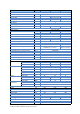
3.3 ACR120HE12 General Data Maximum height Door width Heat medium Heat setting Fan type / dia Fan settings Switching type Weight Electrical Data Supply voltage Total load M M ACR180HE18 4.0 1.2 1.8 Electric heated kW 6 / 12 9 / 18 Crossflow / 150mm 3 AC-ACR-PANEL / SmartElec2 38.0 55.0 kg 415V 3ph 50Hz Motor power Max Starting current* Max Running current* External fuse size amps Programmer keypad Program keypad control wiring Cable terminal size kW A/pha W amps amps A/pha pt. no. 12.4 17.
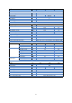
3.4 ACR100SA General Data Maximum height Door width Heat medium Fan type / dia Fan settings Switching type Weight M M 1.2 kg 28 ACR150SA 3.0 1.5 Ambient Crossflow / 100mm 3 AC-ACR-PANEL 34 ACR200SA 2.0 49 Electrical Data Supply voltage Total load Motor power Max Starting current* Max Running current* External fuse size amps Programmer keypad Program keypad control wiring Cable terminal size Mains terminal block position Control terminal block position 230V 1ph 50Hz 0.06 0.09 0.26 0.4 60 90 0.
3.5 ACR120HA ACR180HA General Data Maximum height Door width Heat medium Fan type / dia Fan settings Switching type Weight Electrical Data Supply voltage Total load M M kg 40.0 2 1300 1850 2300 Length mm 1150 Depth (width) Total height* Outlet length Outlet depth (width) Grille height Mounting bracket centres length Side to 1st bracket centre Mounting bracket centres height Top to 1st bracket centre mm mm mm mm mm mm mm mm mm Noise level @ 3M in free field 58.0 230V 1ph 50Hz 0.4 1.6 370 5.
3.
3.
3.8 Program Controller General Data Sensor input NTC Protection 2 x ‘slow blow’ fuse for the protection of the heater switching devices. Fan Output 3 off Relay for High, Medium and Low Fan setting 3A max 240Vac Connection Screw terminals 4 for supply, 6 for heater output, 4 for fan output, 2 for BMS (time) control, 2 for sensor input, 2 for external thermal trip, 2 for external door switch. Supply 230V 1Ph or 415 3Ph dependent on model type. Dimensions Program panel 88mm(L) x 88mm(W) max.
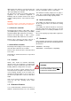
4. Wiring Diagrams. 4.1 Installer Wiring - Electrically Heated 6 & 9kW SINGLE PHASE ONLY The program panel is connected to the base unit via a set of 3 way connectors marked "+12V”, “DATA” and “GND". Interconnecting wiring is via screened twisted pair 28AWG as shown. Max length 50m. It is recommended that this cable is run separately within its own trunking to avoid external interference. * External switch (ie BMS enable) to be volt free and wired via normally open contacts to terminal pair B1, B2.
4.2 Installer Wiring - Electrically Heated 9 & 12kW THREE PHASE ONLY The program panel is connected to the base unit via a set of 3 way connectors marked "+12V”, “DATA” and “GND". Interconnecting wiring is via screened twisted pair 28AWG as shown. Max length 50m. It is recommended that this cable is run separately within its own trunking to avoid external interference. * External switch (ie BMS enable) to be volt free and wired via normally open contacts to terminal pair B1, B2.
4.3 Installer Wiring - Electrically Heated 18kW THREE PHASE ONLY The program panel is connected to the base unit via a set of 3 way connectors marked "+12V”, “DATA” and “GND". Interconnecting wiring is via screened twisted pair 28AWG as shown. Max length 50m. It is recommended that this cable is run separately within its own trunking to avoid external interference. * External switch (ie BMS enable) to be volt free and wired via normally open contacts to terminal pair B1, B2. (Contacts closed to enable).
4.4 Installer Wiring - Ambient The program panel is connected to the base unit via a set of 3 way connectors marked "+12V”, “DATA” and “GND". Interconnecting wiring is via screened twisted pair 28AWG as shown. Max length 50m. It is recommended that this cable is run separately within its own trunking to avoid external interference. * External switch (ie BMS enable) to be volt free and wired via normally open contacts to terminal pair B1, B2. (Contacts closed to enable). Remove factory fitted jumper J1.
4.5 Installer Wiring - LPHW The program panel is connected to the base unit via a set of 3 way connectors marked "+12V”, “DATA” and “GND". Interconnecting wiring is via screened twisted pair 28AWG as shown. Max length 50m. It is recommended that this cable is run separately within its own trunking to avoid external interference. * External switch (ie BMS enable) to be volt free and wired via normally open contacts to terminal pair B1, B2. (Contacts closed to enable). Remove factory fitted jumper J1.
4.
4.
4.
4.
4.10 Factory Wiring - Electrically heated ACR200/ACR180HE 18kW 3Pha X2 S1 GND S2 DATA D1 +12V D2 B1 JJ1 B2 T1 T2 T1 L1 T2 L2 T3 L3 N N F3 F2 F1 AC2-T1 L1 AC1-T1 AC2-T2 L2 AC1-T2 L3 AC2-T3 Overheat Overheat2 AC1-T3 Overheat 1 Elements A2 AC1 A1 T1 L1 T2 L2 T3 L3 Elements Fan Motor A2 AC2 A1 Contractors Terminal E N L3 L2 L1 The element outputs are connected to contactors "AC1” and “AC2” on terminals T1, T2 and T3.
4.11 Factory Wiring - Ambient ACR100/ACR150 S1 GND S2 DATA D1 +12V D2 J1 B1 B2 T1 N N F3 F2 F1 AC2-T1 L1 AC1-T1 AC2-T2 L2 AC1-T2 AC2-T3 L3 AC1-T3 T2 Fan Motor Pcb Terminal Description N Neutral to fan F1 Fan - low speed F2 Fan - medium speed F3 Fan - high speed J1 Factory BMS link The fan output is connected to a 4 way connector marked "N”, “F1”, “F2” and “F3".
4.12 Factory Wiring - Ambient ACR200/ACR120HA/ACR180HA S1 GND S2 DATA D1 +12V D2 B2 T1 N N F3 F2 F1 AC2-T1 L1 AC1-T1 AC2-T2 L2 AC1-T2 AC2-T3 T2 AC1-T3 J2 B1 L3 J1 Fan Motor Pcb Terminal Description N Neutral to fan F1 Fan - low speed F2 Fan - medium speed F3 Fan - high speed J1 Factory BMS link J2 Factory thermal link The fan output is connected to a 4 way connector marked "N”, “F1”, “F2” and “F3".
4.13 Factory Wiring - LPHW ACR100/ACR150 S1 GND S2 DATA D1 +12V D2 J1 B1 B2 T1 N N F3 F2 F1 AC2-T1 L1 AC1-T1 AC2-T2 L2 AC1-T2 AC2-T3 L3 AC1-T3 T2 Fan Motor Pcb Terminal Description N Neutral to fan F1 Fan - low speed F2 Fan - medium speed F3 Fan - high speed J1 Factory BMS link The fan output is connected to a 4 way connector marked "N”, “F1”, “F2” and “F3".
4.14 Factory Wiring - LPHW ACR200/ACR120HW/ACR180HW S1 GND S2 DATA D1 +12V D2 B2 T1 N N F3 F2 F1 AC2-T1 L1 AC1-T1 AC2-T2 L2 AC1-T2 AC2-T3 T2 AC1-T3 J2 B1 L3 J1 Fan Motor Pcb Terminal Description N Neutral to fan F1 Fan - low speed F2 Fan - medium speed F3 Fan - high speed J1 Factory BMS link J2 Factory thermal link The fan output is connected to a 4 way connector marked "N”, “F1”, “F2” and “F3".
4.15 Network Wiring - Electronic controller PROGRAM PANEL (rear view shown) GND DATA +12V Screw terminals Sensor*** screen Door Switch** S1 GND S2 DATA D1 +12V 2 core screened cable Networking D2 B1 B2 External Switch* (located in air curtain 1) T1 T2 AC2-T2 L2 AC1-T2 AC2-T3 L3 AC1-T3 Remove link J1 for external time switch The program panel is connected to the base unit in the first air curtain via a 2 core cable to a 3 way connector marked "+12V”, “DATA” and “GND".
4.16 Installer wiring diagram Electrically heated with SmartElec2 control. 415v 50Hz MAINS SUPPLY PROGRAM PANEL (rear view shown) BASE UNIT (located in air curtain) HE HE 1 2 3 N FAN L2 L1 CHASSIS EARTH HE L3 N FACTORY INSTALLED EARTH LINK. DO NOT REMOVE COMMS RS485 ON 1 terminals as supplied 2 3 TIMER DOOR STAT TEMP EXT 4 TIMER DOOR J1 Optional Sensor*** J2 Pre-wired 4 core screened cable and plugs B.M.S.
4.17 Factory Installed Wiring. Electrically Heated ACR100/ACR150 with SmartElec2 Control. Fan motor FACTORY INSTALLED EARTH LINK. DO NOT REMOVE 1 2 3 N FAN HE HE L2 L1 HE L3 CHASSIS EARTH N BASE UNIT (located in air curtain) TIMER DOOR STAT TEMP EXT ON 1 2 3 4 J1 Outlet Sensor Terminal Description Cable HE Heating elements phase 1 10mm² max HE Heating elements phase 2 10mm² max HE Heating elements phase 3 10mm² max N Neutral to fan 1.5mm² max 1 Fan - low speed 1.
4.18 Factory Installed Wiring. Electrically Heated ACR200/ACR120HE/ACR180HE with SmartElec2. Fan motor FACTORY INSTALLED EARTH LINK.
4.19 Network Wiring Electrically Heated with SmartElec2 Control. BASE UNIT (air curtain '0') Pre-wired 4 core screened cable and plugs COMMS RS485 BASE UNIT (air curtain '1') TIMER DOOR STAT TEMP EXT COMMS RS485 TIMER DOOR STAT TEMP EXT terminals as supplied TIMER DOOR J1 J2 Optional Sensor*** Optional Sensor*** Door Switch** Door Switch** B.M.S. Enable* This diagram refers only to the wiring of 2 or more networked air curtains. (maximum 16 air curtains per control panel).
5. Installation Details. 5.1 Mounting Airbloc units should be installed horizontally directly over the door opening. They are designed for discreet positioning in a suspended ceiling or bulkhead in the doorways of retail or commercial premises. The unit can also be mounted within an optional case for doorways with restricted space or no suspended ceiling or bulkhead.
Step 3 Step 6 Access to the inside of the air curtain grille can be made. Open the grille. The grille is hinged to prevent the inner frame from dropping. Either drop rods or catenary wire (available from manufacturer) can be used to fasten the air curtain to the ceiling support structure. Note When using drop rods the casing mounting brackets are slotted and the mounting plates provided must be used on assembly.
After fitting the product in the ceiling recess and adjusting the height to ensure that the grille sits flush to the ceiling (when re-fitted) take the grille assembly and refit using the screws removed during Step 5. 5.5 Installation details Option SmartElec2 Controller 5.4 Installation details AC-ACR-PANEL programmer The SmartElec2 program panel is installed in a separate housing and connected to a surface mounted back box in a suitable location. Please see fig 7.
5.6 Installation details - LPHW Only Fig.9 LPHW connections. Flow connections To avoid risk of transit damage to the flow and return connections, ON LPHW STANDARD CAPACITY ONLY the heating coil is provided loose inside the case together with the air deflector plate and side supports. NOTE: HIGH CAPACITY LPHW COILS ARE PRE-FITTED. To install, unpack the loose items and identify the two side supports as shown below and fit to the inner side of the case using the screws provided.
5.7 Installation wiring Install the ACR unit using drop rods as previously described. With the grille door open, connect the electrical supply and program panel interconnecting wiring/ factory supplied cables to the relevant terminals on the controller base unit. Connect any interconnecting wiring/factory supplied cables to the programme panel. Connect any optional wiring as required. For full details see wiring diagrams in section 4.
6. Servicing & Maintenance. ALWAYS ENSURE THAT THE MAIN EXTERNAL ELECTRICITY SUPPLY IS SWITCHED OFF BEFORE COMMENCING ANY MAINTENANCE ON THIS HEATER. Step 2 Access to the inside of the air curtain grille can be made. To obtain the best results from the heater, it is essential to avoid the accumulation of dust and dirt within the unit on the air inlet and discharge grilles. For this reason regular cleaning is necessary, paying particular attention to the removal of dirt build up on the rotor blades.
7. Spare parts 7.1 General Description Motor ACR100SE6/ ACR150SE6/ ACR200SE9/ ACR120HE12/ ACR180HE18/ ACR100SE9/ ACR150SE12/ ACR200SE18/ ACR120HW12 ACR180HW18 ACR100SW9/ ACR150SW12 ACR200SW18 /ACR120HA /ACR180HA ACR100SA /ACR150SA /ACR200SA 100003 Contactor (where reqd) 100003 n/a 100535 100012 900078 n/a 900078 Rotor Left Hand 100001 100006 100010 100539 100540 Rotor Right Hand 100002 100007 100011 100536 100537 Thermal cut out (where reqd) 900001 7.
7.3 SmartElec2 controller Due to the nature of it’s construction, it is not advisable to repair damaged electronic components on either the SmartElec2 base unit or Program panel. Description All models Description All models 108221 Control Fuse 900473 SELEC2RP Outdoor sensor SC-OS Base Unit SELEC2BU Data cable c/w plugs Heat Sensor SELEC2HS Program Panel Panel P.C.B 2M 10M 20M 30M 50M 100M SE2-CABLE-2 SE2-CABLE-10 SE2-CABLE-20 SE2-CABLE-30 SE2-CABLE-50 SE2-CABLE-100 900471 Fuse 7.
8. Fault Finding. 8.1 General 8.4 SmartElec2 Controllers. If the air curtain does not operate after running through the detail provided in Section 6, then a suitably competent service engineer should be called to identify the nature of the fault. The SmartElec2 control raises an alarm if any of its inputs are outside their normal working scope. Alarms are displayed on the program panel as a code with a prefix "E". 0 E6 The first number represents the air curtain address. See chart over.
The system can be reset by powering-up the panel whilst holding down the and . buttons. Alternatively, the engineer’s mode automatically self-clears after approximately 10 minutes of non -activity on the switches. The display shows the ‘start’ pattern but then goes blank. Release the buttons where upon the display resumes and the system addressing commences, finding only those air curtains which are actually connected and working.
9. Parts replacement. 9.1.1 Electrical element replacement SE. 9.1.2 Electrical element replacement HE. Step 1 Using a 4mm Allen key slacken the M6 Allen screws at the side of the grille. Access to the inside of the air curtain grille can be made. Open the grille. The grille is hinged to prevent the inner frame from dropping. Step 1 Using a 4mm Allen key slacken screws securing the grille. Remove 4 screws securing the top of the case and remove. Slacken two hinging bolts on both ends.
9.2.1 Rotor and motor replacement SE Step 1 Using a 4mm Allen key slacken the M6 Allen screws at the side of the grille. Access to the inside of the air curtain grille can be made. Open the grille. The grille is hinged to prevent the inner frame from dropping. Note: when refitting ensure that the grub screw bears on the flat of the motor shaft. Step 5 Push the rotor support bracket away from the rotor to release the rotor bearing.
Step 9 Swing the movable bracket clear and remove the motor. Step 4 Turn retaining latch to release chassis. Movable bracket 9.2.2 Rotor and motor replacement HE Step 5 Holding handle, carefully pull motor and air wheel assembly forward. Step 1 Using a pozidrive screwdriver undo screws securing the grille and remove. Remove 4 screws securing the top of the case and remove. Slacken two hinging bolts on both ends. Remove three bolts securing the access plate. Carefully hinge down the access plate.
9.3 LPHW coil replacement. Step 1 Using a 4mm Allen key slacken screws securing the grille. Remove 4 screws securing the top of the case and remove. Slacken two hinging bolts on both ends. Remove three bolts securing the access plate. Carefully hinge down the access plate. Note: Take the weight as access plate swings down. Step 2 Disconnect flow connections with appropriate tools. Step 8 Disconnect the wires from the motor to the controller base unit.
10. User Instructions. fig.12. AC-ACR-PANEL Programmer 10.1.1 Keypad Buttons The button will allow you to navigate. The button will allow you to increase the setting. The button will allow you to decrease the setting. 10.1.2 Operation On first power up, the display panel will have the following default settings: F. 0 H. 0 1. 16 2. 7 D. 2 (no fan) (no heat) (°C. Heat set point - Auto mode only) (°C.
The next parameter will either turn the unit On or Off. To turn the unit Off, press the flashing. button. ‘On’ will start Press the button. ‘Off’ will start flashing. Press the button to confirm new setting. To turn the unit On, press the flashing. Press the button. ‘Off’ will start button to alter to ‘On. Press the button to confirm new setting. A delay of 7 seconds will return to the ‘F’ Fan parameter. 10.1.3 Engineers settings 10.1.3.
Press the button, setting “A.Of” will appear. This setting will enable the Auto Mode. (Range: On/Off) To alter the setting, press the button then the buttons to toggle between the “A.Of” and or “A.On” modes. “A.On” enables the air curtain to run under automatic control from the optional outdoor sensor. “A.Of” enables the air curtain to run under normal control. To return to the engineering setting mode press and hold the button for 5 seconds.
10.2 Option SmartElec2 Controller If the air curtain is in operation and under heat demand, a ‘decimal point’ is shown 0. 23 after the air curtain address. 0 F1 10.2.3 OFF mode. During normal operation, press and hold the button for approximately two seconds. The display blanks until you release the button. The heating and fans are now turned off. Releasing the button in less than this time and the action has no effect. fig.13. SmartElec2 Programmer 10.2.
10.2.5 Set-up configurations 10.2.6 Engineers settings 10.2.5.1 Set fan speed Other options are available in engineer’s mode. Once the display becomes illuminated press the the button once. Display shows the fan speed. To access the engineers mode either: Press to increase fan speed. until the display goes blank, then press Press to decrease fan speed. press and hold the briefly. The display will show F1 Speed 1 0 F2 Speed 2 0 F3 Speed 3 0 F0 Fan ‘off’ to set heat ‘on’.
The temperature setting when the door link is open circuit is accessed by pressing the . button until the display shows 0 t0 Use the and buttons to alter the temperature value. Display Meaning 0 t0 Heat off 0 t1 5°C 0 t2 10°C 0 t3 15°C 0 t4 20°C 0 t5 25°C 0 t6 30°C 0 t7 35°C 10.2.6.3 All air curtains This function is accessed by pressing the button until the display shows ≡ 25 Using this setting all air curtains in a network respond to the same settings.
Note: If any address is altered after initial power up or an air curtain removed after initial installation, the keypad will also retain the original address although unable to respond. 10.2.6.6 Temperature limits This function is accessed by pressing the button until the display shows - 35 and respectively i.e. maximum and _ 16 minimum set limits for set temperature. To remove this unwanted address(s) follow the details in 10.2.7 Power-up Manual Reset.
10.2.
Document reference number GB/AIR/048/0213