OWNER_____________________________________ VESSEL_____________________________________ RADIO CALL SIGN____________________________ Product Support Manual GlobalFix™ 406 Emergency Position Indicating Radio Beacon Product No. 2742 Cat.1 Product No. 2744 Cat.2 RLB-35 Y1-03-0157 Rev. F FCC Type Accepted ACR Electronics, Inc. 5757 Ravenswood Road Fort Lauderdale, Fl 33312 Tel : +1(954) 981-3333 Fax: +1 (954) 983-5087 www.acrelectronics.com Email: Info@acrelectronics.
* * * WARNING * * * THIS TRANSMITTER IS AUTHORIZED FOR USE ONLY DURING SITUATIONS OF GRAVE AND IMMINENT DANGER DELIBERATE MISUSE MAY INCUR A SEVERE PENALTY Magnet Safe Distance 1m (3.3 ft) Keep this beacon a safe distance away from all magnetic sources Stereo Speaker Safe Distance 1m (3.
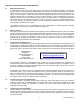
Foreword Congratulations and thank you for purchasing the ACR GlobalFix™ Emergency Position Indicating Radio Beacon. The combination of superior design, high quality raw materials and quality controlled manufacturing produce a product that will perform for years to come. The test facility at ACR can reproduce some of the harshest environmental conditions known to man. This assures that the products we manufacture can stand up to the rigors found in a marine environment.
SECTION 1 - REGISTRATION OF 406 MHZ BEACONS 1.1 Registration Importance It is mandatory that the owner of this 406 MHz beacon registers it with the National Authority.* All 406 MHz beacons transmit a Unique Identifier Number (UIN) when activated. This UIN is programmed in the beacon based on the country in which the beacon was purchased. Registration provides the search and rescue forces with up to date emergency contact information, which will speed up the launch of a rescue operation.
1.6 Registration Outside the United States In countries other than the United States, 406 MHz beacons are registered with that country’s National Authority at the time of purchase. The sales agent should assist in filling out the forms and sending to that country’s National Authority. To verify that the unit is properly programmed for that country, view the UIN label on the side of the unit.
SECTION 3 - INSTALLATION 3.1 Mounting Location The location selected must be sufficiently rigid to support the weight of the total installation and at the same time consider vibration, exposure to the elements, exposure to surrounding hazards, such as equipment movement, doors being opened, accidental covering, personnel traffic, etc., and yet be readily accessible at all times for the emergency use for which the beacon is intended.
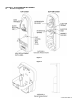
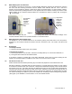
SECTION 4 – ACTIVATION AND DEPLOYMENT 4.1 Bracket Configuration Figure 1 Figure 2 4 Y1-03-0157 Rev.
4.2 Configuration Overview The GlobalFix™ beacon (Product No. 2742) Cat. 1 is designed to be automatically deployed and activated. The beacon may also be hand held on the deck of vessels, or floated in water and attached to a raft or life vest with the lanyard provided. (Product No. 2744 Cat. 2 is designed to be manually deployed from its bracket.) The beacon is designed to operate best while floating in water. Hand held operation should be avoided when possible.
4.5 Manual Deployment and Activation The GlobalFix™ (Product No. 2742) Cat. 1 can be manually deployed by removing the retaining pin, removing the cover, and then removing the beacon from the bracket. Once removed, both the Cat. 1 and Cat. 2 beacons can be activated by placing in water OR by lifting the thumb switch to a vertical position, sliding it toward the antenna and pushing back down to the opposite side of the EPIRB.
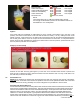
TEST Initial Test Start Check Data Integrity Check 406 MHz Synthesizer Check RF Power/Battery Check Internal GPS Successful Test SUCCESS Red LED Red LED Beep, Red LED Beep, Red LED Beep, Red LED Beep, Green LED, Strobe FAIL Test stopped Test stopped Test stopped Test stopped NOTE: The homing beacon at 121.5 MHz is inhibited during self test.
functioning properly and that the beacon is in a location or environment where it can receive the necessary signals from satellites. If the GPS does not acquire good positional data, the GPS will turn OFF after 10 minutes and there will be no successful green LED indication. This test should never be performed more than once during the five-year life of the battery pack to prevent excessive current drain! The beacon must remain under observation to witness the results of the test.
5.4 Shore Based Maintenance (SBM) for SOLAS Vessels , IMO Circ. 1040 The Maritime Safety Committee approved guidelines for shore-based maintenance of satellite EPIRBs, for the purpose of establishing standardized procedures and minimum levels of service for the testing and maintenance of satellite EPIRBs. MSC/Circ. 1039. First Shore Based Maintenance on all ACR EPIRBs is due at the date of the first battery replacement. See our website at www. acrelectronics.com for more information. 5.
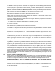
Figure 7- Satellite Coverage Figure 8- GEOSAR Satellite Orbits Figure 9- GPS Satellite Orbits SECTION 7 - AUTHORIZATIONS The GlobalFix™ EPIRB meets the requirements of Federal Communications Commission (FCC) Part 80 (Product No. 2742 Cat. 1, 2744 Cat. 2); and GMDSS (Product No. 2742) and MED. 7.1 Characteristics The GlobalFix™ EPIRB is a buoyant, battery operated unit. The beacon case, with its external antenna, is waterproof.
121.5 MHz Transmitter Frequency Frequency Tolerance Output Power Modulation Type Antenna Frequency Polarization VSWR GPS Antenna Battery Life Operating Replacement Interval General/Environmental Size (less Antenna) Antenna Height EPIRB Material 7.4 Accessories Mounting Case (Cat. 1) Size Release System 121.5 MHz ±50 ppm 25 mW PEP AM (3K20A3X) 406 & 121.500 MHz Vertical Less than 1.5/1 12 Channel Parallel Receiver 48 hours minimum 5 years or after use in an emergency 7.0 x 4.25 x 3.62 in. (17.8 x 10.
ACR Electronics, Inc. 5757 Ravenswood Road, Ft. Lauderdale, FL 33312-6645 Tel: +1 (954) 981 3333 Fax: +1 (954) 983-5087 http://www.acrelectronics.
ACR Electronics, Inc. 5757 Ravenswood Road, Ft. Lauderdale, FL 33312-6645 Tel: +1 (954) 981 3333 Fax: +1 (954) 983-5087 www.acrelectronics.