™ GlobalWatch 2 AIS Installation Manual Y1-03-0183-1 Rev. A Version 1.0 Y1-03-0183-1 Rev.
Please read this first! Warning: Although ACR strives for accuracy in all its publications; this material may contain errors or omissions, and is subject to change without prior notice. ACR shall not be made liable for any specific, indirect, incidental or consequential damages as a result of its use. ACR components may only be used in safety of life devices or systems, with the express written approval of ACR, as the failure of such components could cause the failure of the ACR device or system.
GlobalWatch2TM AIS Installation Manual Index 1 GENERAL INTRODUCTION ................................................................................ 1 1.1 2 Installation Requirements............................................................................... 3 Installation Overview ...................................................................................... 3 Installation of VHF / GPS Antennas ...............................................................
History of Changes Date 2004-09-01 Version 1.0.0 GlobalWatch2TM AIS Installation Manual Status Released Comments III Responsible Team Version 1.0 Y1-03-0183-1 Rev.
1 General Introduction 1.1 Description of AIS What does the abbreviation AIS stand for? AIS stands for: “Automatic Identification System” What is AIS? According to IALA regulations, AIS is defined as follows: Very simply, the AIS is a broadcast Transponder system, operating in the VHF maritime mobile Band. It is capable of sending ship information such as identification, position course, speed and more, to other ships and to shore.
2 GlobalWatch2TM AIS 2.1 System Overview Unlike other AIS devices, the GlobalWatch2TM AIS combines all required functions into one cabinet. Additionally, the GlobalWatch2TM AIS gives the operator a number of additional features (easy mounting & installation, environmental protection, smallest dimensions). GlobalWatch2TM AIS Installation Manual 2 Version 1.0 Y1-03-0183-1 Rev.
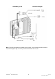
3 Installation 3.1 Installation Requirements General Requirements Please note that international conventions, regulations, instructions and guidelines have to be adhered to when installing the GlobalWatch2TM AIS. The following points must be observed before installation can commence: - Permission by the local authority to install such a device must be granted. Trained service personnel must undertake the installation. The GlobalWatch2TM AIS must be fitted in a suitable place on the bridge.
GlobalWatch2TM AIS Connection Diagram Note: The ACR connection box includes a fuse of 6,3A. If it is not used, then the unit has to be protected against high current by an external slow blow fuse of 6,3A. GlobalWatch2TM AIS Installation Manual 4 Version 1.0 Y1-03-0183-1 Rev.
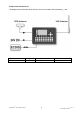
Components and Interfaces The diagram below illustrates which devices can be connected to the GlobalWatch2TM AIS. Interface ECDIS GlobalWatch2TM AIS Installation Manual Designation Speed CH 4 38400bps 5 Direction Input/Output Version 1.0 Y1-03-0183-1 Rev.
3.3 Installation of VHF / GPS Antennas Interference to the Ship’s VHF Radiotelephone The AIS ship borne equipment, like any other ship borne transceiver operating in the VHF maritime band, may cause interference to a ship’s VHF radiotelephone. Because AIS is a digital system, this interference may occur as a periodic (e.g. every 20 seconds) soft clicking sound on the ship’s radiotelephone.
Coaxial cables should be installed in separate signal cable channels/tubes, and at least 10 cm away from any power supply cables. Crossing of cables should take place at right angles (90°). Coaxial cables should not be exposed to sharp bends, which may lead to changes to the characteristic impedance of the cable. The minimum bend radius should be 5 times the cables outside diameter.
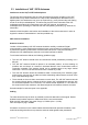
4 Starting the GlobalWatch2TM AIS After completing the hardware, antennas and external equipment installation, the initial system start-up can commence. To start the system, connect the GlobalWatch2TM AIS with the power supply. The next step is to enter the configuration like password and the MMSI number. L 4.1 MMSI Number: BoatU.S is an organization for advancing the interests of boaters. The “BoatU.S. MMSI Program” has been certified by both the Federal Communications Commission and the U.S.
4.2 Service and User Passwords: The Transponder system is equipped with two separate Passwords. 1) The User Password, which is the lower security level allows access to all menus except Menu 6: Service Configuration - please refer to the User Manual for further details on password protection. 2) The Service Password is required in order to enter the Service Configuration Menu.
N 1^24' E 0^17' |1>0.10|2>1.30|3>1.80nm ---------------------------------------++++++++++++++++++++++++++++++++++++++++ Service password protected! Please enter service password: ++++++++++++++++++++++++++++++++++++++++ ---------------------------------------| Enter | | | Exit Select Submenu 1 “Change Service Password” with cursor button [Up] & [Down] by pressing Nr. 1 on the keyboard. N 1^21' E 0^14' |1>0.01|2>1.30|3>1.80nm |---------------------------------| 6. Service Configuration -----| | | +- 1.
Enter the new Password: Repeat the new Password: A minimum of 4, a maximum of 8 characters are allowed. Should the new password include numbers, use the shift key to generate them. N 1^25' E 0^18' |1>0.10|2>1.30|3>1.80nm ******* Change Service Password ******** Enter new password : Repeat new password: {Length: 4..8 characters} ---------------------------------------| Save | | | Back Press Save to store the change.
Select Submenu 1 “Change User Password” with cursor button [Up] & [Down] by pressing Nr. 1 on the keyboard. N 1^21' E 0^14' |1>0.01|2>1.30|3>1.80nm |---------------------------------| 6-2. User Password Settings -----| | | +- 1. Change User Password View | +- 2. Change Password Protection | -----| | Msg. | | -----| | Displ| ---------------------------------------NUM| Select->| | |<-Back Enter the new Password: Repeat the new Password: A minimum of 4, a maximum of 8 characters are allowed.
4.3 Changing the MMSI / IMO Numbers Select “Service Configuration” from the Main Menu with the cursor button [Up] & [Down] or press Nr. 6 on the keyboard. N 1^19' E 0^13' |1>0.01|2>1.30|3>1.80nm |---------------------------------| Menu -----| | | +- 1. Messages View | +- 2. AIS Status | +- 3. Voyage Settings -----| +- 4. Ship Settings | +- 5. Transponder Configuration Msg. | +- 6. Service Configuration | +- 7.
Select Submenu 3 “Change MMSI/IMO” with cursor button [Up] & [Down] by pressing Nr. 3 on the keyboard. N 1^21' E 0^14' |1>0.01|2>1.30|3>1.80nm |---------------------------------| 6. Service Configuration -----| | | +- 1. Change Service Password View | +- 2. User Password Settings | +- 3. Change MMSI / IMO -----| +- 4. Restore Factory Settings | Msg. | | -----| | Displ| ---------------------------------------NUM| Select->| | |<-Back Input new MMSI / IMO Numbers and press [Save] to store input data.
4.4 Inputing Voyage Related Data – (User Password Protected) Select “Voyage Settings” from the Main Menu with the cursor button [Up] & [Down] or press Nr. 3 on the keyboard Note: The default User Password is set to “NAUT” – please reconfigure it immediately after Transponder initial operation N 1^20' E 0^13' |1> N/A|2>0.00|3>0.10nm |---------------------------------| Menu -----| | | +- 1. Messages View | +- 2. AIS Status | +- 3. Voyage Settings -----| +- 4. Ship Settings | +- 5.
Scroll the Voyage Data Fields with [Enter] and input own vessel data. Select a default Cargo Type and NavStat Setting with the cursor buttons [Left] & [Right]. Save the new settings by pressing [Save], and return to the Main Menu Screen by pressing [Exit]. Press [Back] to return to the Main Menu without saving any changes. N 1^18' E 0^12' |1>0.01|2>1.30|3>1.80nm *********** Voyage Settings ************ Cargo : Draught :24.8m PoB :1 Dest. :CASABLANCA ETA :10/13 12:31 NavStat.
N 1^23' E 0^16' |1>0.01|2>1.30|3>1.80nm ---------------------------------------++++++++++++++++++++++++++++++++++++++++ User password protected! Please enter user password: ++++++++++++++++++++++++++++++++++++++++ ---------------------------------------| Enter | | | Exit Scroll the Ship Settings Fields with [Enter] and input own vessel data.
5 Troubleshooting 5.1 Reading and understanding Alarms: The GlobalWatch2TM AIS differentiates between Alarm and TXT messages. An Alarm informs the user about major system malfunctions and failings in the connected sensors. The Alarm Status informs the user about all active Alarms. The Alarm will be disabled and deleted from the Alarm Status, as soon as the displayed problem has been rectified. The TXT status displays additional sensor information and the UTC clock status.
5.
5.3 Text Messages Cause/Source Reaction of the System / Remedy Internal GPS Reaction: the transponder unit continues operation using indirect or semaphore synchronisation Remedy: Check GPS Antenna for AIS.
6 Accessories The Standard Set for the GlobalWatch2TM AIS consists of the following products: Drawing Number Category Description GlobalWatch2TM AIS Basic Kit 1 GlobalWatch2 AIS Transponder Installation and user manual, 3 caps of plug 1 cable clamp (M5 thread) 3 angles + 3 mounting screws (screw bolt + square nut) Mounting: Antennas: Kit bracket-mounting + 2 wing bolts + 4 screws TM GPS Antenna GPS4 (Procom) + mounting Glomex VHF antenna RA 109 sls + mounting kit Cables and Interfaces GPS / VHF e
8 Technical Information PHYSICAL Size in mm / inch (w) Size in mm / inch (h) Size in mm / inch (d) Weight Operating Temperature 201,26mm / 7,92inch 60mm / 2,36inch 281,26mm / 11,07inch 2490g / 5,50pound -15°C to +55°C / 5°F to 131°F POWER SUPPLY Supply Voltage (galvanic isolated) Input Current 24 V DC (-10% +30%) min.7 A (24V) INTERFACES CH4 ECDIS Port (In- / Output) AIS targets, AIS messages 12 channel differential 12 satellites sim.
8.1 ANNEX These documents are included on the following pages: (1) MMSI Form (2) Dimensional Drawings (3) Connection Drawings (4) Quick Replacement Guide (5) Transponder Installation Checklist GlobalWatch2TM AIS Installation Manual 23 Version 1.0 Y1-03-0183-1 Rev.
The BoatU.S. MMSI Program has been certified by both the Federal Communications Commission and the U.S. Coast Guard to assign MMSI numbers to vessels with DSC capable radios that are not required by law to carry a radio, and do not make international voyages or communications. Following is a printer friendly MMSI# Assignment Form. You may download this form and return it to BoatU.S. via mail or fax.
MMSI ASSIGNMENT FORM * Denotes a required field. These fields must be completed in order to receive an MMSI#.
SHIP CLASSIFICATION TABLE RECREATIONAL VESSELS DUN - KETCH MTB - MOTOR BOAT SLO - SLOOP YAT - YACHT GOL - SCHOONER VLR - SAILING SHIP COMMERCIAL VESSELS & SHIPS OF WAR ACV - AIR CUSHION VEHICLE AVI - DISPATCH VESSEL BAR - LIGHTER BLN - WHALER BLS - BUOY SHIP CA - CARGO SHIP CAB - COASTER CGT - COAST GUARD CHA - BARGE CIM - CEMENT CARRIER CIT - TANKER CON - CONTAINER SHIP COR - CORVETTE DES - DESTROYER DIV - USED BY DIVERS DOU - CUSTOMS LAUNCH DRG - DREDGER ECO - TRAINING SHIP EXP - RESEARCH SHIP FPS - FAS
Y1-03-0183-1 Rev.
Y1-03-0183-1 Rev.
Y1-03-0183-1 Rev.
Y1-03-0183-1 Rev.
Y1-03-0183-1 Rev.
Y1-03-0183-1 Rev.
1 2 3 4 5 6 7 8 A A 1,5m ± 10mm 1 50±5 4 3) 4) 1 B 16,17,33 48,49,32 1) + 1) - B 6 2) C Weitergabe sowie Vervielfaltigung dieser Unterlage, Verwertung und Mitteilung ihres Inhaltes nicht gestattet, soweit nicht ausdrucklich zugestanden. Zuwiederhandlungen verpflichten zu Schadenersatz. Alle Rechte vorbehalten, insbesonders fur den Fall der Patenterteilung oder GM-Eintragung. 1,2 6,7 6) CH 4 ext.
1 2 3 4 5 6 7 8 A A 10m ±10mm 4 2) 3) 1) B 1,2 1) 7 1) 6 1) B 3 C C 1 Weitergabe sowie Vervielfaltigung dieser Unterlage, Verwertung und Mitteilung ihres Inhaltes nicht gestattet, soweit nicht ausdrucklich zugestanden. Zuwiederhandlungen verpflichten zu Schadenersatz. Alle Rechte vorbehalten, insbesonders fur den Fall der Patenterteilung oder GM-Eintragung. 5 7 D A1 VHF-Stecker A2 TNC A3 D 6 1) Pos 4 auf Stecker 1, 6, 7 anschlagen (gecrimpt bzw.
Y1-03-0183-1 Rev. A Source, Draw.-No.
Quick Replacement Guide X-Pack DS 1. Prepare the following tools: Screwdrivers, spanners User Password: your personal password (factory default setting is ‘NAUT’) 2. Read out your Transponder configuration Steps to do this: Press Menu Press 2 2.AIS Status Press 2 2.Own Ship Data Write down the current configuration settings here: IMO No. : Dest : ShipName : EAT : ShipType : MMSI : Length : CS : Cargo : Beam : Draught : Press Menu Press 4 Password [UserPassword] [Enter 4.
6. Connect cables 6.1. AIS-Cable to screw on 6.2. VHF/GPS Cable to screw on 7. Mount the replacement unit 7.1. Bracket Mounting 7.2. Frame Mounting 8. Key in the configuration settings from above: Following steps to key in the Configuration Press Menu Press 6 Password NAUT [Enter Press 3 6.Service Configuration ] (Default Factory Password) 3.
Page 1 of 2 Transponder Installation Checklist Please fill out your contact and vessel details below: Vessel Location (Port and country) Ship Name Company Name Installer Company Name Reseller Contact Name Contact Telephone number Contact Email Please fill out the Transponder details below: You will find the serial Number on the back side under the barcode.
Page 2 of 2 Sensor CH1 (optional) Sensor CH2 (optional) Sensor CH3 (optional) Channel 4 Channel 5 (optional) Channel 8 (optional) Channel 9 (optional) Converter Type Transponder Configuration: IMO No (if available) MMSI ShipName CS ShipType Length Beam Draught Cargo Destination RefPtExt: A B C D RefPtInt: A B C D BaudRate Sensor1: BaudRate Sensor2: BaudRate Sensor3: Functionality Check: Now check your Transponder functionality - the correct values for LAT, LON, SOG, COG, and Time should appear