Y1-03-0244B i
About Cobham Life Support, ACR Products Cobham Life Support, ACR Products www.acrelectronics.com, designs and manufactures a complete line of safety and survival products including EPIRBs, PLBs, AIS, SARTs, Strobe Lights, Life Jacket Lights, Search Lights and safety accessories. The quality systems of this facility have been registered by UL to the ISO 9001:2008 Series Standards.
Table of Contents STEP ONE - REGISTERING YOUR BEACON ______________________ 4 STEP TWO - HOW THE BEACON WORKS _______________________ 6 STEP THREE - MAINTAINING YOUR PLB ______________________ 15 APPENDIX A - ACCESSORIES _______________________________ 19 APPENDIX B - USER INTERFACE: SPECIAL ICONS ________________ 21 APPENDIX C - USER INTERFACE: DIGITAL DISPLAY- OPERATION ___ 22 APPENDIX D - USER INTERFACE: DIGITAL DISPLAY - SELF-TEST ____ 25 APPENDIX E - USER INTERFACE: DIGITAL DISPLAY -LONG GPS TEST_ 28
STEP ONE - REGISTERING YOUR BEACON Why is registration important? As the owner of this 406 MHz beacon, it is mandatory that you register it with the PLB national authority of your country: It is the law. Please note that all 406 MHz beacons are required to have their registration updated every two years by the owner. Your personalized ID code programmed inside each beacon is transmitted to Search and Rescue (SAR).
What country should I register in? The beacon must be registered in the country of the owner’s residence. If the beacon is not programmed to that country’s code and protocol, and the residence is outside of the USA, the beacon needs to be reprogrammed. Additionally, the beacon must be reprogrammed if you, as the owner, move out of the country where the beacon is registered.
Registration in Canada Canadian residents can register online at: http://canadianbeaconregistry.forces.gc.ca/ or contact the Canadian Beacon Registry by phone at: 877-406-7671 or by fax at: 877-406-3298.
The 406 MHz signal is detected by multiple satellites and from that information the location of the beacon can be calculated. This data alone is sufficient for SAR to find persons or ships in distress in a reasonable timeframe. However, as a further enhancement, some beacons have a GPS engine onboard. This feature allows the beacon to acquire current location coordinates from an internal GPS receiver. The purpose of this feature is to send an even more precise location of the beacon to the satellites, i.e.
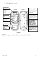
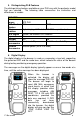
4. Anatomy of your beacon Digital display Antenna: Wrapped around beacon FRONT BACK UIN Label: Applied at the factory, the 15 character hexadecimal number is unique to each beacon. Multi-language label: This optional label may be applied for ease of use. Antenna latch Activation button cover Registration decal supplied by some countries: Once the beacon is registered, the label goes here. Keypad GPS antenna location Battery expiration label with the month/ year the battery needs to be replaced.
5. Distinguishing PLB Features The distinguishing features available on your PLB vary with the particular model that you selected. The following table summarizes the similarities and differences in models.
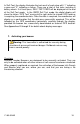
In Self-Test, the display illustrates the test result of each step with “√” indicating a pass and “X” indicating a failure. There are a total of five tests, including a battery check. If all tests pass, SELF-TEST PASS will be displayed at the end of the Self-Test mode. In the GNSS Self Test mode, the digital display will show the letters “GPS Test” moving left to right while the internal GPS receiver is acquiring the coordinate data.
NOTE: The appearance of your key pad may vary from this picture.
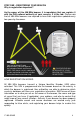
Steps to activate (406 MHz and 121.5 MHz) To activate your beacon in a distress situation, follow these steps (see Figure 3 below). 1) Unclip the antenna from the case. 2) Move it into the upright position 3) Depress the ON/OFF ( ) button for 1 full second. You will see the Red LED flashing and the display reads “PLB ON”. Your beacon is now activated. While transmitting your distress signal, the red LED will flash once every 2 seconds, alerting you that your beacon is active. Figure 3 8.
The same GPS data will be sent with each 406 MHz signal for the next twenty minutes. At that time the internal GPS will start up again, search to find your LAT/LON and incorporate it into your next 406 MHz signal. If for any reason the internal GPS cannot update your LAT/LON, your last position will be used for the next four hours. At that time the green LED will stop blinking and the red LED will flash once every 2 seconds until new GPS data is obtained. 10.
12. Preventing false alerts A false alert is any activation of the beacon, intentional or otherwise, that does not result from a situation of grave and imminent danger. Be sure to do the following to help minimize false alerts: // Register your beacon. This does not reduce false alert rates; however, when the beacon is properly registered, the situation can usually be resolved with a phone call. // Be careful with whom you leave your beacon.
To report false alert in the United States, contact the AFRCC: United States Air Force Rescue Tel: 1-800-851-3051 Coordination Center (AFRCC) To report false alerts outside of the USA, contact the national authority where your beacon is registered. STEP THREE - MAINTAINING YOUR PLB 1. Routine Maintenance Carefully inspect the beacon case for any visible cracks. Cracks may admit moisture, which could falsely activate the beacon or otherwise cause a malfunction.
3. Self-test ACR strongly recommends performing the Self-test once per month, or at least two weeks prior to a trip allowing enough time for service should your beacon require it. A Self-test is initiated by holding the Self-test button for at least ½ second and less than 5 seconds. Your beacon will flash the green LED to signify the test has begun and the Digital Display will show Pass or Fail message. The green LED will flash a second time to indicate that the self test was successful.
5. GPS Testing (GNSS Self-Test) This test is NOT required as 100% of all GPS receivers that leave ACR have been tested to ensure they perform correctly. However, if you would like to ensure your GPS receiver is working, please follow these instructions very closely. CAUTION: For PLB-350C models, the following test can not be performed more than sixty times during the life of the battery pack. Once this GPS testing feature reaches 60 times, the feature will be disabled by internal software.
6. Changing ownership or contact information As the owner of the beacon, it is your responsibility to advise the national authority of any change in your registration information. If you are transferring the beacon to a new owner, you are required to inform the national authority. You can do this by using their online database or by letter, fax or telephone and informing the authority of the name and address of the new owner.
APPENDIX A - ACCESSORIES 1. Multi-Function Belt Clip The SARLink™ View comes standard with a multifunction belt clip. To install the clip, simply align the bottom tabs on the clip with the insert holes located on the bottom of the beacon. Snap the clip in place by pressing the top of the clip so that the two top tabs engage in the two insert holes on the top of the beacon (see Figure 5). To remove the clip, push up and back on the top tabs one at a time to disengage the clip from the beacon.
2. Attachment Clip The AquaLink™ View comes standard with an attachment clip. To install the clip, simply align the bottom tabs on the clip with the insert holes located on the bottom of the beacon. Snap the clip in place by pressing the top of the clip so that the two top tabs engage in the two insert holes on the top of the beacon (see Figure 6). To remove the clip, push up and back on the top tabs one at a time to disengage from the beacon.
APPENDIX B - USER INTERFACE: SPECIAL ICONS Characters displayed during beacon operation include the following: The battery gauge appears on certain screens to indicate the remaining level of battery charge The gauge illustrates the remaining charge in the battery as a percent of the total possible charge, e.g., The gauge will show the system to be charged in the following increments: 100, 75, 50 and 25%.
APPENDIX C - USER INTERFACE: DIGITAL DISPLAY DURING OPERATION The following chart describes the audio-visual feedback the beacon provides during activation. The messages on the digital display typically appear as one or two words at a time, until the entire message has been displayed.
GPS SENT G This message appears only if GPS data was acquired 121.5 ON G R The system reports that the 121.5 MHz homing signal is on. Search and Rescue (SAR) personnel use this frequency when arriving close to the scene. If this message is accompanied by a green LED flash, the GPS coordinates have been sent. If accompanied by a red LED flash, the GPS coordinates have not been sent.
LEAVE G PLB ON UNTIL RES Q R The system reminds you that leaving the beacon on continuously gives the best assurance of being rescued. SAR groups need the ongoing transmissions from the beacon to most effectively find you. If this message is accompanied by a green LED flash, the GPS coordinates have been sent. If accompanied by a red LED flash, the GPS coordinates have not been sent.
APPENDIX D - USER INTERFACE: DIGITAL DISPLAY DURING SELF-TEST The following chart describes the display and audio-visual feedback the beacon provides during Self-Test. The messages on the digital display typically appear as one or two words at a time, until the entire message has been displayed. AquaLink™ View and SARLink™ View Display, LED/ Audio Signaling and Description of Operation Beacon Self-Test has been initiated, and the ACR Electronics’ Welcome Page appears.
406 RF TEST √ G The fourth test checks for 406 MHz signal strength/RF power. If power is adequate the system passes. 406 RF TEST R The fourth test checks for 406 MHz signal strength/RF power. If power is not adequate the system fails. GPS TEST √ G The fifth test checks GPS engine readiness. If the GPS is ready the beacon passes. GPS TEST R The fifth test checks GPS engine readiness. If the GPS is not ready the beacon fails.
BATT LOW This message appears if Self-Test has passed, but the battery is low. Take the beacon to an authorized Service Center for a battery replacement. NOTES regarding Self-Test logic: 1.) When one of the tests fail, the system bypasses the remaining tests and goes to SELF-TEST FAIL 2.) The only exception to #1 is that if the battery fails, the other tests are still performed. The system will tell the user if there are other system failures by flashing SELF-TEST FAIL.
APPENDIX E - USER INTERFACE: DIGITAL DISPLAY DURING EXTENDED GPS TEST The following chart describes the display and audio-visual feedback the beacon provides during extended GPS Test. The messages on the digital display typically appear as one or two words at a time, until the entire message has been displayed. AquaLink™ View and SARLink™ View display, LED/ Audio Signaling and Description of Operation LONG GPS DATA TEST START The system informs you that the extended GPS test has initiated.
APPENDIX F - THE COSPAS-SARSAT SYSTEM 1. General overview Beacons transmit to the satellite portion of the Cospas-Sarsat system. Cospas-Sarsat satellites are an international system that utilizes Russian Federation and United States’ low altitude, near-polar orbiting satellites (LEOSAR). These satellites assist in detecting and locating activated 406 MHz satellite beacons. Cospas-Sarsat satellites receive distress signals from beacons transmitting on the frequency of 406 MHz.
APPENDIX G - TECHNICAL SPECIFICATIONS 406 MHz Transmitter Frequency 406 MHz Output Power greater than 5 watts (typical: 6.3 watts) Frequency Stability ±2 parts per billion/100ms Digital Message: Format Long message Serialized1* Message protocol Standard Location Duration 520 ms Rate 400 bps Encoding Biphase L Modulation ±1.1 radians peak 1* Beacons are shipped from ACR with a Serialized code but can be reprogrammed at a service center to other coded formats including nationality of registration. 121.
APPENDIX H - WARRANTY, USEFUL LIFE POLICY, NOTICES Limited Warranty This product is warranted against factory defects in material and workmanship for a period of 1 (one) year* from date of purchase or receipt as a gift. During the warranty period ACR Electronics, Inc. will repair or, at its option, replace the unit at no cost to you for labor, materials and return transportation from ACR. For further assistance, please contact our Technical Service Department at ACR Electronics, Inc.
APPENDIX I – RESTRICTIONS ON USE and EC DOC Europe – R&TTE Directive The following countries place no restrictions on the use of this product: Austria Bulgaria Cyprus Czech Republic Denmark Estonia Finland Greece Iceland Ireland Italy The Netherlands Norway Portugal Romania Slovak Republic Sweden Switzerland/Liechtenstein United Kingdom The following countries require a license for this product: France Germany Hungary Latvia Lithuania Luxembourg Spain The following country only allows terrestrial use and re
EC DECLARATION OF CONFORMITY ACR Electronics, Inc. hereby declares that the following products are in conformity with Directive 1999/5/EC of the European Parliament and of the Council of 9 March 1999 on Radio Equipment and Telecommunications Terminal Equipment (R&TTE), and has been type examined as described in this Declaration.