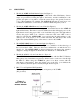
PRODUCT SUPPORT MANUAL Y1-03-0116 Rev. C L-32 Field Marker Lighting System L-32 L-32 RC L-32 RCL CC-1 ACR Electronics, Inc. 5757 Ravenswood Road Fort Lauderdale, Fl 33312 +1(954) 981-3333 •Fax +1 (954) 983-5087 www.acrelectronics.com Email: Info@acrelectronics.
TABLE OF CONTENTS SECTION DESCRIPTION PAGE 1.0 ........................................ Introduction.......................................................... 2 2.0 ........................................ Complete System Overview .................................. 3 3.0 ........................................ Subsystems ........................................................... 4 4.0 ........................................ System Set-up and Operation ................................ 5 5.0 ...........
FIELD MARKER LIGHT SYSTEM FEATURES: 1.0 • Remote control operation • Supports any number of incandescent lights • Configurable to any requirement • Color or infrared filters (optional) • • Easily transportable Water resistant INTRODUCTION The ACR Field Marker Light System is an evolutionary refinement of signaling technology that exemplifies how we can improve upon and redefine the application of existing systems.
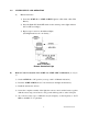
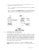
Since the introduction of the Field Marker System, ACR has expanded it to be available in a sequential version as well. 2.0 COMPLETE SYSTEM OVERVIEW The ACR/L-32 or L-32RCL may be plugged directly into the BA-4386 or BA-5598 Battery and act as a stand alone, manually controlled light. For remote controlled operation, the ACR/L-32 may be inserted into the ACR/L32RC which in turn is inserted into the battery.
3.0 SUBSYSTEMS 1. The Model ACR/L-32 Field Marker Light (See Figure 1) The ACR/L-32 light is designed to plug into a BA-4386 or BA-5598 Battery. Canvas straps are provided for holding the light to the battery, and the combination to the ground (use spikes or long nails to secure the canvas strap to the ground). Lenses in color or IR transmitting are available. The ACR/L-32 light may be used alone or in combination with Items 2, 3 and 4 below, for Remote Radio Frequency control. 2.
4.0 SYSTEM SET-UP AND OPERATION A) Manual Activation 1) Insert the ACR/L-32 or ACR/L-32 RCL Light into a BA-4386 or BA-5598 Battery. 2) Press the Push-ON, Push-OFF switch for the desired position (light will turn ON or OFF accordingly). 3) Repeat steps 1 and 2 for all additional lights. (Each light must have its own battery.
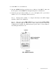
6) Set the PRC-77 to a transmit mode. 7) Turn the ACR/CC-1 ON and position it next to hand-set of the PRC-77, make sure the microphone of the ACR/CC-1 is facing the microphone on the hand-set. 8) On the key pad, press button number 1, 2, or 3 to turn light(s) ON, or press button number 4, 5, 6, or 7 to turn light(s) OFF (see Note 2). Note 1: Pressing button number 7 on keypad will always turn OFF all lights regardless of their code configuration.
Figure 5: ACR/L-32 / L-32 RC Combo Remote Light System C. Remote Controlled Activation of the ACR/L-32RCL unit (See Figure 6) 1) Insert the ACR/L-32RCL Remote Controlled Light directly into the battery. 2) Plug antenna onto banana plug. 3) Secure the complete assembly of the light, and battery together with the canvas hold down strap and secure the light to the ground with a long nail or stake down pins.
7) Codes 4, 5, 6 are pre-programmed as "OFF" code at the factory and 1, 2, 3 are preprogrammed as "ON" codes. (See Note 2) Note 1: Code number 7 is always the universal "OFF" and cannot be reprogrammed for any other function. Note 2: The codes on the ACR/L-32RCL Remote Controlled Light are factory preset, however, other code combinations are able to be set by the user. For further information, please refer to section number 5 - Customizing the Activation Code.
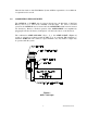
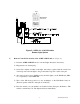
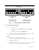
Wall of case 2 3 4 5 6 1 2 3 4 5 6 ON 6.0 ON OFF or Deactivation Codes This depicts a code 1 will turn the light "ON" This depicts a code 3 will turn the light "OFF" Figure 7: 1 ON or Activation Codes SETTING THE ON AND OFF REMOTE CODES CODE CONFIGURATION SET-UP A) B) To access the DIP switch 1. Remove rear cover of the ACR/L-32RC unit by removing 4 phillipshead screws. 2. Unscrew the lens assembly on the ACR/L-32RCL Pick code number(s) (1 through 6) which will turn the unit "ON".
Example 1: Light shall turn "ON" when code 1 is selected. Set-up: D) Set DIP switch number 1 to "ON" position (away from the case wall), set all others (2, 3, 4, 5, and 6) to "OFF" position (toward the case wall). Setting the "OFF" code selector Set the DIP switches of the "OFF" code selector to the "ON" position for desired "OFF" activation code(s). Ensure that number(s) was not used for the "ON" activation code. Set all other DIP switches to "OFF" position.
REPLACEMENT PARTS ITEM NO. ACR/PART NUMBER DESCRIPTION 1 4491 ACR/L-32 2 4492 ACR/L-32RC Unit 3 4493 ACR/CC-1 4 4494 ACR / L-32 RCL 5 9000.1 Lens, Clear (Standard) 9000.2 Lens, Infra-Red (Optional) 9000.3 Lens, Red (Optional) 9000.4 Lens, Blue (Optional) 9000.
NOTES: 12 Y1-03-0116 Rev.