Please read this first! Warning: Although ACR strives for accuracy in all its publications; this material may contain errors or omissions, and is subject to change without prior notice. ACR shall not be made liable for any specific, indirect, incidental or consequential damages as a result of its use. ACR components may only be used in safety of life devices or systems, with the express written approval of ACR, as the failure of such components could cause the failure of the ACR device or system.
NAUTICAST™-INLAND Installation Manual Index Page Number 1 GENERAL INTRODUCTION ...............................................................................................................................................1 1.1 Description of AIS ......................................................................................................................................................1 1.2 AIS in an Operational Environment ........................................................................
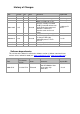
History of Changes Date 2005-11-01 2006-07-14 2006-10-11 Version 1.0.0 1.0.1 1.0.2 Rev. A B C Status Released Released Released 2008-12-05 1.0.5 D Released 2008-12-05 1.0.6 E Released 2009-09-15 1.0.8 F Released 2009-09-27 2010-05-11 1.0.8 1.0.
1 General Introduction 1.1 Description of AIS What does the abbreviation AIS stand for? AIS stands for: “Automatic Identification System” What is AIS? According to IALA regulations, AIS is defined as follows: Very simply, the AIS is a broadcast Transponder system, operating in the VHF maritime mobile Band. It is capable of sending ship information such as identification, position course, speed and more, to other ships and to shore.
1.2 AIS in an Operational Environment This illustration depicts a typical AIS System, where two or more AIS equipped vessels (and shore based systems) are automatically communicating with each other. On the bottom, a typical NAUTICAST™ installation in a common environment is shown. The NAUTICAST™ is connected to the vessels emergency power supply, and in connection with the VHF, and GPS-Antennas, the minimal requirements for Transponder operation are fulfilled.
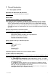
1.3 AIS Networks The scenario below shows a full AIS coverage area (including all applications and complete shore infrastructure). The Carriage Requirement currently applies to SOLAS Vessels and will be extended on Inland Waterways.
2 NAUTICAST 2.1 System Overview Unlike other AIS devices, the NAUTICAST™ combines all required functions into one cabinet. Additionally, the NAUTICAST™ gives the operator a number of additional features (easy mounting & installation, environmental protection and smallest dimensions).
3 Installation IMPORTANT: AUTHORITIES MANDATE that after the physical installation has been successfully completed, all ships data and settings be entered into the AIS transponder. See Section 4 for further instructions. 3.1 Installation Requirements General Requirements Please note that international conventions, regulations, instructions and guidelines have to be adhered to when installing the NAUTICAST™.
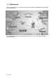
Step-by-Step Installation Procedure: Mount the NAUTICAST™ close to ships operation workstation for traffic surveillance and maneuvering. Use the VHF adapter cable (P/N 2612) together with the VHF plug and TNC plug to connect the VHF and GPS antenna cables and antennas. The sensors, ECDIS, PC, pilot case, long range devices and auxiliary displays can be connected to the NAUTICAST™ cabinet by the AIS cable by means of the connection box.
Components and Interfaces The diagram below illustrates which devices can be connected to the NAUTICAST™. For a detailed description of sensor connecting e.g. an existing Gyro to the NAUTICAST™ refer to Chapter 3.5 “Sensor Interface Definitions.” 3.
3.4 Interface NMEA Description: 3.4.1 Sensor - Interface CH1, CH2, CH3 Refer to Chapter 3.8 for detailed information on Sensor - Interface and Configuration. 3.4.
3.4.3 Pilot Port CH 5 The used sentence formatters for the pilot plug are the same as those listed for the ECDIS port. Note: A pilot input/output port is part of an AIS Class A installation. A plug connected to this port should be installed on the bridge near the pilot‟s operating position, so that a pilot can connect a Personal Pilot Unit (PPU) if required. Also, a power connector for the pilot unit should be available nearby.
3.4.5 DGPS – DGNSS Channel 9 Field / Protocol information: All fields are provided with further information; please refer to ITU-R M.823-2 / RTCM SC 104 for detailed field information. 3.4.6 Alarm Circuit – BIIT Channel 10 The AIS requires that an alarm output (relay) must be connected to an audible alarm device or the ships alarm system, if available.
3.5 Sensor Interface Definitions All interface ports of the NAUTICAST comply with IEC-61162-1 / -2 and NMEA-0183 HS 3.0 specifications (aligned to RS422 parameters). 3.5.1 Talker drive circuits The maximum output current is Imax = 50mA on each port. The drive circuit meets the requirements of ITU-T V.11. 3.5.2 Listener Receiver Circuits Multiple listeners may be connected to a single talker. Optional termination resistors (120Ohm) for the input lines are provided in the connection box.
3.6 Sensor notes External Sensor The AIS has interfaces (configurable as IEC 61162-1 or 61162-2) for position, bottom track (BT) speed, heading and rate of turn (ROT) sensors. In general, sensors installed in compliance with other carriage requirements of SOLAS Chapter V should be connected to the AIS System.*1. The sensor information transmitted by AIS should be the same information being used for navigation of the ship.
3.7 Sensor Hardware Installation: 3.7.1 Installation of an RS422 serial interface: In most cases, the output from a GPS is already being used by existing navigation equipment. It is possible to split an RS 422 output for two devices. If the signal becomes too low, then an NMEA splitter has to be used. Example for single talk multi-listener connection: Shields A - IN B + IN C (GND) Talker (e.g.
3.8 Sensor Software Configuration 3.8.1 Introduction The NAUTICAST™ AIS requires a connection to various sensor devices. Sensor Configuration should enable compatibility with existing navigation devises aboard any vessel. This chapter deals with several ways to configure the NAUTICAST™ and to comply with the requirements of the specific sensor interfaces. Configuration and display is visible on two screens of the Sensor Configuration Menu.
After accessing the Sensor Configuration menu this main configuration screen is active: N 1o19' E 0o12' |1> N/A|2>0.00|3>0.
*********** Sensor Settings ************ ************************************** * * * Please stay... * * analyze Sensor 1..3 * * this takes max. 30sec. * * * ************************************** ---------------------------------------| | | | Back It is possible to interrupt this process by pressing the “Back” - Button [M8]. After the analysis is complete, the Transponder will list the data used for the AIS operation. N 1o18' E 0o12' |1> N/A|2>0.00|3>0.
3.8.3 Real-Time Analysis of NMEA Data Streams After these configuration procedures, an overview of the current Sensor Software Configuration has been attained. This filtered NMEA data can be analyzed further. The data source is shown on the screen below. The source can be internal or external devices, the received NMEA sentence and the channel where this data was identified (Sensor 1, 2, 3 or calculated), as well as the measured update rate. N 1o19' E 0o13' |1> N/A|2>0.00|3>0.
Each time the analysis process for sensor configuration is undertaken; a trace file (see below) is automatically generated and sent out to the ECDIS-Port. This output can also be used as a Sensor Configuration Report. $PNAUSCA,4800,4800,4800,1 $PNAUSCD,------------ Sensor Settings -----------$PNAUSCD,Date : 06/22/2004 08:57:05 $PNAUSCD,Hardware: AIS Transponder Class A $PNAUSCD,Software: 2.0.0.11R3 $PNAUSCD,SW Stamp: Jun 14 2004 11:46:10 $PNAUSCD,LAT : N 53o30.123' LON : E 10o 1.
3.8.4 Sensor Monitoring for Problem Analysis For specific information on a particular sensor, the NMEA input data can be monitored and is listed on the AIS display. N 1o21' E 0o15' |1> N/A|2>0.00|3>0.
3.8.5 Priority Handling of Sensor Sentence This table shows the priority handling of NMEA sentences. The sentences which are treated with higher priority are listed first. Positioning System Time of Position Latitude/Longitude Position accuracy Rate of Turn(ROT) Reference Datum Speed over Ground Heading RAIM Indicator Source Priority HIGH GNS GLL GGA RMC ROT DTM VBW VTG OSD RMC HDT OSD GBS LOW 3.8.6 Supported NMEA-0183 Sentences DTM - Reference 1 2 3 4 5 6 7 8 9 | | | | | | | | | $--DTM,ccc,a,x.
6) GPS Quality Indicator, 0 - fix not available, 1 - GPS fix, 2 - Differential GPS fix 7) Number of satellites in view, 00 - 12 8) Horizontal Dilution of precision 9) Antenna Altitude above/below mean-sea-level (geoid) 10) Units of antenna altitude, meters 11) Geoidal separation, the difference between the WGS-84 earth ellipsoid and mean-sea-level (geoid), \-\ means mean-sea-level below ellipsoid 12) Units of geoidal separation, meters 13) Age of differential GPS data, time in seconds since last SC104 type
5:LoInd 6:Acc 7:Sat RMC - Minimum Navigation Information 12 1 2 3 4 5 6 7 8 9 10 11| 13 | | | | | | | | | | | | | $--RMC,hhmmss.ss,A,llll.ll,a,yyyyy.yy,a,x.x,x.x,ddmmyy,x.
Used Fields: 1,5,6,7,8,9 1:COG 5:SOG 6:SOGIn 7:SOG 8:SOGIn 9:Valid OSD - Ship Data 1 2 3 4 5 6 7 8 9 10 | | | | | | | | | | $--OSD,x.x,A,x.x,a,x.x,a,x.x,x.x,a*hh Field Numbers: 1) Heading, degrees true 2) Status, A = Data Valid 3) Vessel Course, degrees True 4) Course Reference 5) Vessel Speed 6) Speed Reference 7) Vessel Set, degrees True 8) Vessel drift (speed) 9) Speed Units 10) CRC Used Fields: 1,2,3,4,5,6,9 1:HDT 2:HDTVal 3:COG 5:SOG 6:SOGRef 9:SOGInd 4:COGRef HDT - True 1 2 3 | | | $--HDT,x.
3.8.7 Calculated Values Processed dynamic ship data such as position, SOG etc. is generated by NMEA sentences. Exceptions: If "Calc" is displayed on the sensor analyze screen, this means that this sentence is used for calculating dynamic ship data. ROT out of HDT ROT direction left / right -/+ will be calculated out of the HDT Message, if a TIROT sentence (only “TI”-Talker devices are valid) is not connected.
3.
Black BK White WH Red RD Green GN Brown BR Blue BL Orange OR Yellow YL Violet VI Gray SL(Slate) Pink PK 3.
3.
3.12 Communication Cable RS232 (Sub-D 50 Socket) BlueSign Switch BlueSign Switch 28 44 RS232 SUB-DB9 CH15_RxD CH15_TxD CH15_gnd 32 15 49 Communication PC 3 2 5 Cable 2635 (NAU-B502) includes a RS232 SUB-DB9 connector for PC communication and flying leads for connection to a Blue Sign Switch (user-provided and Single throw On/Off required.
3.13 Installation of VHF / GPS Antennas Interference to the Ship’s VHF Radiotelephone The AIS ship borne equipment, like any other ship borne transceiver operating in the VHF maritime band, may cause interference to a ship‟s VHF radiotelephone. Because AIS is a digital system, this interference may occur as a periodic (e.g. every 20 seconds) soft clicking sound on the ship‟s radiotelephone.
All outdoor connectors on the coaxial cables should be fitted with preventive isolation, such as shrink-stocking with silicone to protect the antenna cable against water penetration. Coaxial cables should be installed in separate signal cable channels/tubes, and at least 10 cm away from any power supply cables. Crossing of cables should take place at right angles (90°). Coaxial cables should not be exposed to sharp bends, which may lead to changes to the characteristic impedance of the cable.
Menu „GPS Settings: Select from the Main Menu “Transponder Configuration ” Number 5. Menu is USER password protected. The default password from the factory is mentioned on your AIS display at the protection foil. Please see the appendix in your User Manual for additional password information.. Enter User Password and use the up and down arrows on keypad to select “6. GPS settings” or “by pressing number 6 on the keypad. N 1o19' E 0o13' |1>0.01|2>1.30|3>1.
GPS module: The screen provides means to switch the GPS Module between the „<µBlox>‟ or „‟. You can force the AIS to search again for the GPS Module installed. Selecting the wrong type of GPS module may result in invalid position information and/or malfunction so that your AIS can not operate correct. Select and with [Left] & [Right] arrows the option to search which module is installed Please mention the system will restart automatically when saving these setting later. .
The position of the VHF and GNSS – antennas must be added to the existing antenna layout of the vessel. 3.14 Power Supply The NAUTICAST™ must be supplied from the emergency power source. A new battery capacity calculation must be undertaken. See sample in 9.
4 Starting the NAUTICAST™ 4.1 Initial Set Up of the NAUTICAST™ for operation ATTENTION: AUTHORITIES MANADATE THAT YOU ENTER THIS INFORMATION. After installing the antennas and hardware the following User, Voyage related and Ship Settings data needs to be entered. Upon Start-up (Applying power) enter the following information. a) Enter MMSI Number - See paragraph 4.2 on entering information. During the initial boot or after “factory settings” the user is asked to enter a valid MMSI number.
4.2 Entering the MMSI / IMO / DAC / ESN Numbers Select from the Main Menu “Service Configuration” Number 6. This option requires the SERVICE password. The default password from the factory is mentioned on your AIS display at the protection foil. Please see the appendix in your User Manual for additional password information. Enter Service Password and use the up and down arrows on keypad to select “Change MMSI / IMO” than press M5 “Select” or “by pressing number 3 on the keypad.
N 1o21' E 0o14' |1> N/A|2>0.00|3>0.10nm ********** Change MMSI / IMO *********** MMSI :119302468 IMO No.:303174162 ---------------------------------------NUM| Save | | | Back Select Submenu 4 “Change DAC / ESN” with cursor button [Up] & [Down] by pressing Nr. 4 on the keyboard. N 1o21' E 0o14' |1>0.01|2>1.30|3>1.80nm |---------------------------------| 6. Service Configuration -----| | | +- 1. Change Service Password View | +- 2. User Password Settings | +- 3. Change MMSI / IMO -----| +- 4.
4.3 Entering Ship Settings Select from the Main Menu “4. Ship Settings” This option requires the USER password. The default password from the factory is mentioned on your AIS display at the protection foil. Please see the appendix in your User Manual for additional password information. Enter Password and use the up and down arrows to edit Ship Settings then press Enter or the numeric reference on the keypad to select and edit. Save after editing. Main Menu Example: N 1 o23' E 0 o16' |1>0.01|2>1.30|3>1.
Setting the Internal and External GPS Antenna Position. Note: It is critical for the proper orientation of your ship to other AIS users to enter this data accurately. Example: Length of ship = 220m and Beam = 43m. GPS ANTENNA location on ship (is x in above Menu example) is located 200 meters from bow (A) and 33 Meters from Starboard side (D). Note: If no external GPS is connected, then enter same data as for internal GPS. External GPS antenna reference point must be filled in before you can save. Ref.
4.4 Entering Voyage Related Data Select from the Main Menu “3. Voyage Settings” This option requires the USER password. The default password from the factory is mentioned on your AIS display at the protection foil. Please see the appendix in your User Manual for additional password information. Enter Password and use the up and down arrows to edit Voyage Related data then press Enter or the numeric reference on the keypad to select and edit. Save after editing.
N 1 o31' E 0 o24' |1>0.01|2>1.30|3>1.80nm ---------------------------------------++++++++++++++++++++++++++++++++++++++++ User password protected! Please enter user password: ++++++++++++++++++++++++++++++++++++++++ ---------------------------------------| Enter | | | Exit Select Submenu 1 “General Settings” with cursor button [Up] & [Down] by pressing Nr. 1 on the keyboard. N 1 o18' E 0 o12' |1>0.01|2>1.30|3>1.80nm |---------------------------------| 3. Voyage Settings -----| | | +- 1.
Select Submenu 2 “Cargo/Voyage Settings” with cursor button [Up] & [Down] or by pressing Nr. 2 on the keyboard. Toggle the values for the ERI ship type (see section 7.1), the hazardous cargo by the number of Blue Cones [0-3, B-Flag, Default/Unknown], and the loaded / unloaded status Un/ Loaded [Loaded, Unloaded]. Save the new settings by pressing [Save], and return to the Main Menu Screen by pressing [Exit].
Select Submenu 4 “Destination” with cursor button [Up] & [Down] by pressing Nr. 4 on the keyboard. Select between mask input and direct input of the destrination string. Mask input: Scroll the Data Fields with [Enter] and input the UN destination codes as well as the ETA (estimated time of arrival) data. Save the new settings by pressing [Save], and return to the Main Menu Screen by pressing [Exit]. Press [Back] to return to the Main Menu without saving any changes. N 1o18' E 0o12' |1>0.01|2>1.30|3>1.
4.5 Entering Inland AIS Configuration Select from the Main Menu “5. Transponder Configuration” This option requires the USER password. The default password from the factory is mentioned on your AIS display at the protection foil. Please see the appendix in your User Manual for additional password information. Enter User Password and press [Enter] or [M5]. N48^12' E 16^26' |1> N/A|2> N/A|3> N/Anm |---------------------------------| Menu -----| | | +- 1. Messages View | +- 2. AIS Status | +- 3.
Select Submenu 7 “Inland AIS Configuration” with cursor button [Up] & [Down] by pressing Nr. 7 on the keyboard. N48^12' E 16^26' |1> N/A|2> N/A|3> N/Anm |---------------------------------| 5. Transponder Configuration -----| | | +- 1. Change User Password View | +- 2. Region Settings | +- 3. Alarm Settings -----| +- 4. Interrogation Settings | +- 5. Sensor Settings Msg. | +- 6. GPS Settings | +- 7.
4.6 Service and User Passwords WARNING: It is very important that the Service password not be lost. Keeping the password in a second location may be wise. Record your custom service and user passwords in the table provided in the appendix of your User Manual. Memorizing the password is best. If you lose this password, you cannot make any further configuration changes: Access to the AIS is blocked. Another master key is not available and the unit would have to be returned to the ACR Service centre.
Service Menu Example: N48^12' E 16^26' |1>0.00|2>0.00| * 2S |---------------------------------| 6. Service Configuration -----| | | +- 1. Change Service Password View | +- 2. User Password Settings | +- 3. Change MMSI / IMO -----| +- 4. Change DAC / ENI | +- 5. Change AIS Mode Msg. | +- 6. Restore Factory Settings | -----| | Displ| ---------------------------------------NUM|Select->| | |<-Back Service Password Menu Example: N 1o25' E 0o18' |1>0.10|2>1.30|3>1.
N48^12' E 16^26' |1>0.00|2>0.00| * 2S |---------------------------------| 6. Service Configuration -----| | | +- 1. Change Service Password View | +- 2. User Password Settings | +- 3. Change MMSI / IMO -----| +- 4. Change DAC / ENI | +- 5. Change AIS Mode Msg. | +- 6. Restore Factory Settings | -----| | Displ| ---------------------------------------NUM|Select->| | |<-Back Select Submenu 1 “Change User Password” with cursor button [Up] & [Down] by pressing Number 1 on the keyboard. N 1o21' E 0o14' |1>0.
5 Troubleshooting 5.1 Reading and understanding Alarms: The NAUTICAST differentiates between Alarm and TXT messages. An Alarm informs the user about major system malfunctions and failings in the connected sensors. The Alarm Status informs the user about all active Alarms. The Alarm will be disabled and deleted from the Alarm Status, as soon as the displayed problem has been rectified. The TXT status displays additional sensor information and the UTC clock status. See tables (Section 5.2 and 5.
5.2 Alarm Codes ID Description Text 01 AIS: Tx malfunction Cause/Source VHF Antenna, cabling AIS: Antenna VSWR exceeds limit VHF antenna, 02 (VSWR - Voltage Standing Wave installation Ratio) 03 AIS: Rx channel 1 malfunction 04 AIS; Rx channel 2 malfunction Internal error 05 AIS: Rx channel 70 malfunction 06 AIS: General failure AIS; External EPFS lost (EPFS = 25 electronic Position Fixing System such as GPS) Reaction: The transponder unit stops transmission.
5.3 Text Messages ID Description Text Cause/Source Reaction of the System / Remedy 07 AIS: UTC clock lost Internal GPS Reaction: the transponder unit continues operation using indirect or semaphore synchronisation Remedy: Check GPS Antenna for AIS.
6 Accessories The following material is included with the NAUTICAST™. 1 NAUTICAST™ Inland AIS Transponder 1 installation manual, 1 user Manual 3 caps of plug 1 cable clamp (M5 thread) 1 guide plate Kit 3 angles + 3 mounting screws (screw bolt + square nut) The NAUTICAST™ Inland AIS is supplied with some of the components listed below (contents depend on customer requirements).
7 Technical Information PHYSICAL Size in mm / inch (w) Size in mm / inch (h) Size in mm / inch (d) Weight Operating Temperature 281,26mm / 11,07inch 60mm / 2,36inch 201,26mm / 7,92inch 2490g / 5,50pound -15°C to +55°C / 5°F to 131°F POWER SUPPLY Supply Voltage (galvanic isolated) Input Current 24 V DC (-10% +30%) min.7 A (24V) INTERFACES Number of Data Ports IEC 61162-1/2 ITU-R M.823-2 Bitrate CH1 Sensor Input; (i.E.: GPS) CH2 Sensor Input; (i.E.: GYRO) CH3 Sensor Input; (i.E.
7.
8380 C Pushtow, eight barges at least one tanker or gas barge 8 0 Tanker All ships of this type 8 0 Tanker All ships of this type 8400 V Tug, single 5 2 Tugs - 8410 No Tug, one or more tows 3 1 Vessel Towing 8420 C Tug, assisting a vessel or linked combination 3 1 Vessel Towing 8430 V Pushboat, single 9 9 Other types of Ship No additional information 8440 V Passenger ship, ferry, cruise ship, red cross ship 6 9 Passenger Sips No additional information 8441 V Ferry 6 9 Pa
9 Appendix 9.1 Samples for battery calculation 9.1.1 Typical Installation GMDSS Battery size calculation for 1 hour (Battery size calculation based on the IMO regulations Chapter IV - Reg.13) Ship Name Battery capacity Battery Type QMIII 230Ah 2x (12V / 135) Area A1, A2, A3 Battery located in battery chest on observation deck Pos Qty. Equipment I-max I-standby Total (A) (A) (A) (I-max/2 + I-standby )*Qty.
9.1.2 RM GMDSS Compact-Console Area A3 with 250 W MF/HF GMDSS Reserve Battery Calculation ( 24 V DC ) for Raytheon Marine GmbH GMDSS Compact-Console Area A3 with 250 W MF/HF According to IMO Regulation COMSAR/Circ.16 4. March 1998 A: with Emergency Generator (SOLAS IV 13.2 ) The GMDSS equipment shall be able to operate one (1) hour on reserve power with 50% of time in transmission mode and 50% in receiving mode. B: without Emergency Generator (SOLAS IV 13.
Calculation: Case A: 1h x ( 0.5 I TX + I RX + I Add ) x 1.4 = 44.06 Ah recommend battery capacity is 86 Ah Charger: I Charg x 0.1 I Batt/h = 8.6 A recommend charger is type 20 A Case B: 6h x ( 0.5 I TX + I RX + I Add ) x 1.4 = 264.39 Ah The battery calculation should not be used for uninterruptible power supply (UPS) configuration 9.
58 Y1-03-0212H 5757 Ravenswood Road Fort Lauderdale, FL 33312 ACR Electronics
457 5757 Ravenswood Road Fort Lauderdale, FL 33312 ACR Electronics DIMENSIONAL DRAWING FOR Nauticast AIS optional mounting kits 70 [2,756] 246 [9,685] 145.
60 Y1-03-0212H 5757 Ravenswood Road Fort Lauderdale, FL 33312 ACR Electronics ACR P/N 2610
Y1-03-0212H 61 5757 Ravenswood Road Fort Lauderdale, FL 33312 ACR Electronics ACR P/N 2640
A B C D 4 4 CH 4 EXT DISPLAY (18 AWG) J1 2 J1 21 22 20 18 19 16, 17, 33 48, 49, 32 1 THIS DOCUMENT AND THE DATA DISCLOSED HEREIN OR HEREWITH IS PROPERTY OF AND BELONGS TO ACR ELECTRONICS, INC. FT LAUDERDALE, FL. IT IS FURNISHED IN CONFIDENCE SOLELY FOR INFORMATIONAL PURPOSES. IT IS NOT TO BE REPRODUCED, USED OR DISCLOSED IN WHOLE OR IN PART TO ANYONE WITHOUT THE PERMISSION OF ACR. 62 Y1-03-0212H 3 J2 4 3 5 2 1 (22 AWG) + (18 AWG) - 3 TWISTED PAIR WHITE BROWN 1.5M .
A B C D 4 4 1 CH 4 EXT DISPLAY (18 AWG) J1 J1 21 22 20 18 19 16, 17, 33 48, 49, 32 THIS DOCUMENT AND THE DATA DISCLOSED HEREIN OR HEREWITH IS PROPERTY OF AND BELONGS TO ACR ELECTRONICS, INC. FT LAUDERDALE, FL. IT IS FURNISHED IN CONFIDENCE SOLELY FOR INFORMATIONAL PURPOSES. IT IS NOT TO BE REPRODUCED, USED OR DISCLOSED IN WHOLE OR IN PART TO ANYONE WITHOUT THE PERMISSION OF ACR. Y1-03-0212H 63 3 J2 4 3 5 2 1 (22 AWG) + (18 AWG) - 3 TWISTED PAIR WHITE BROWN SCHEMATIC 2 3 1.5M .
A B C D 8 8 50 PIN D SUB MALE 32 15 CH15_RxD CH15_TxD Y1-03-0212H 7 49 44 CH15_gnd 28 BlueSign Switch 7 BlueSign Switch THIS DOCUMENT AND THE DATA DISCLOSED HEREIN OR HEREWITH IS PROPERTY OF AND BELONGS TO ACR ELECTRONICS, INC. FT LAUDERDALE, FL. IT IS FURNISHED IN CONFIDENCE SOLELY FOR INFORMATIONAL PURPOSES. IT IS NOT TO BE REPRODUCED, USED OR DISCLOSED IN WHOLE OR IN PART TO ANYONE WITHOUT THE PERMISSION OF ACR.
A B Y1-03-0212H 65 32 15 49 CH15_TxD CH15_gnd 28 44 CH15_RxD 4 BlueSign Switch BlueSign Switch 50-pin D sub male connector DSUB 9 PIN 5 3 2 ALL 22 Awg THIS DOCUMENT AND THE DATA DISCLOSED HEREIN OR HEREWITH IS PROPERTY OF AND BELONGS TO ACR ELECTRONICS, INC. FT LAUDERDALE, FL. IT IS FURNISHED IN CONFIDENCE SOLELY FOR INFORMATIONAL PURPOSES. IT IS NOT TO BE REPRODUCED, USED OR DISCLOSED IN WHOLE OR IN PART TO ANYONE WITHOUT THE PERMISSION OF ACR. 4 3 3 1.5M .1M 2 5757 RAVENSWOOD RD. FT.
66 Y1-03-0212H 1. Mating connectors for cable are A1-03-0339 (TNC Male) and A1-03-0337 (N male) RG214 Crimp connectors. 2.
Y1-03-0212H 67 2613 GPS/VHF Interface Cable, 10 meters (VHF) (GPS)
68 Y1-03-0212H
THIS DOCUMENT AND THE DATA DISCLOSED HEREIN OR HEREWITH IS PROPERTY OF AND BELONGS TO ACR ELECTRONICS, INC. FT LAUDERDALE, FL. IT IS FURNISHED IN CONFIDENCE SOLELY FOR INFORMATIONAL PURPOSES. IT IS NOT TO BE REPRODUCED, USED OR DISCLOSED IN WHOLE OR IN PART TO ANYONE WITHOUT THE PERMISSION OF ACR. WIRE SPECIFICATION: CABLE MODEL: YMM-O INNER WIRE JACKET COLOR: BROWN & BLUE STRANDED WIRE OUTER JACKET MATERIAL: PVC OUTER JACKET COLOR: BLACK OR GREY RATED VOLTAGE...............................................
Input voltage range Output voltage Intermittent output power Transient voltage protection Electrostatic voltage protection Output noise Off load current (quiescent current) Power conversion efficiency Isolation Operating temperature Storage temperature Operating humidity Casework Connections Output indicator Mounting method Safe area protection: Over current Over heat Transients Catastrophic failure Approvals Markings Switch Power 240W (10 A) Isolated 24Vdc ± 30% 27.
38 230 34 44 GPS 4 PROCOM RECEIVING ANTENNA DRAWING NO.
A B C D 4 3.4 7 TYP. 3 PLACES 4 A 120.0° 120° Y1-03-0212H ITEM 4 70 61 47.2 40 7.5° ITEM 3 70 28 THIS DOCUMENT AND THE DATA DISCLOSED HEREIN OR HEREWITH IS PROPERTY OF AND BELONGS TO ACR ELECTRONICS, INC. FT LAUDERDALE, FL. IT IS FURNISHED IN CONFIDENCE SOLELY FOR INFORMATIONAL PURPOSES. IT IS NOT TO BE REPRODUCED, USED OR DISCLOSED IN WHOLE OR IN PART TO ANYONE WITHOUT THE PERMISSION OF ACR. 72 13 A 120.0° 120° 2.1 6.5 80.
Electrical Specifications: Dielectric Antenna Center Frequency 1575.42MHz±3 MHz V.S.W.R 1.5:1 Band Width ±5 MHz Impendence 50 ohm Peak Gain > 3dBic Based on 7×7cm ground plane Gain Coverage > -4dBic at –90°<0<+90° (over 75% Volume) Polarization RHCP LNA/Filter A3-06-2539 LNA Gain without cable 28 dB Typical A3-06-2539-1 LNA Gain with cable 17 dB to 20 dB Noise Figure 1.5dB Filter Out Band Attenuation (f0=1575.42 MHZ) 7dB Min f0+/-20MHZ 20dB Min f0+/-50MHZ 30dB Min f0+/-100MHZ V.S.W.R < 2.0 DC Voltage 5.
74 Y1-03-0212H DECK MOUNTING PLASTIC P/N: 2627 STANTION OR RAIL MOUNTING METAL P/N: 2626 OR GPS ANTENNA P/N: 2637 OR 2639 OR P/N: 2821 DECK MOUNTING METAL FOR SCREW PATTERN DETAILS PLEASE SEE THE PART NUMBER DRAWINGS MOUNTING OPTIONS FOR GPS ANTENNA
A B C D 8 8 110 112±2 40 11 7 60 9 11 THIS DOCUMENT AND THE DATA DISCLOSED HEREIN OR HEREWITH IS PROPERTY OF AND BELONGS TO ACR ELECTRONICS, INC. FT LAUDERDALE, FL. IT IS FURNISHED IN CONFIDENCE SOLELY FOR INFORMATIONAL PURPOSES. IT IS NOT TO BE REPRODUCED, USED OR DISCLOSED IN WHOLE OR IN PART TO ANYONE WITHOUT THE PERMISSION OF ACR. Y1-03-0212H 75 7 42.5 7 95 M8X1.25 THREAD 110 20 25.4 1"X14 THREAD 25 6 5.1 60 85 6 14 8 27 5 4. ITEMS COME TOGETHER IN A BOX 3.
A B C D 4 100 70 35 Y1-03-0212H 4 3. ITEMS COME INDIVIDUALLY PACKAGED 3. COLOR: WHITE 2. MATERIAL: NYLON 1. GLOMEX P/N: V9175 NOTES: R5 3 22 25 THIS DOCUMENT AND THE DATA DISCLOSED HEREIN OR HEREWITH IS PROPERTY OF AND BELONGS TO ACR ELECTRONICS, INC. FT LAUDERDALE, FL. IT IS FURNISHED IN CONFIDENCE SOLELY FOR INFORMATIONAL PURPOSES. IT IS NOT TO BE REPRODUCED, USED OR DISCLOSED IN WHOLE OR IN PART TO ANYONE WITHOUT THE PERMISSION OF ACR. 76 3 7.3 93 COUNTER SINK TYP. 6.
A B Y1-03-0212H 77 2.1 4 2. FINISH: POLISHED 3.04 1. MATERIAL: 304 STAINLESS STEEL NOTES: 3X .25 THRU THIS DOCUMENT AND THE DATA DISCLOSED HEREIN OR HEREWITH IS PROPERTY OF AND BELONGS TO ACR ELECTRONICS, INC. FT LAUDERDALE, FL. IT IS FURNISHED IN CONFIDENCE SOLELY FOR INFORMATIONAL PURPOSES. IT IS NOT TO BE REPRODUCED, USED OR DISCLOSED IN WHOLE OR IN PART TO ANYONE WITHOUT THE PERMISSION OF ACR. 4 .84 3 3 4.0 2 SPECIFICATION CONTROL DRAWING 1.
Antenna Width Dimensions: Antenna Tip, plastic cover. Antenna Whip, 17-7PH SS, Electro polished Base, Plating Nickel/Chrome Mounting Hole, Dimension Detail ACR ELECTRONICS INC.
Antenna Dimension and Part Description: Part Descriptions: 1.) Antenna Whip 2.) Base of whip 3.) Coil housing cover – White nylon. 4.) Coil housing – Aluminum White. 5.) Antenna Connector – SO239, female. 6.) Locking washer and nut. 7.) Mounting bracket 8.) Set screw x2. ACR ELECTRONICS INC.
80 Y1-03-0212H 5757 Ravenswood Road Fort Lauderdale, FL 33312 ACR Electronics ACR P/N 2621
TECHNICAL DATA: Electrical specifications: Frequency range Nominal impedance Power rating Gain Polarization Power GPS Noise figure, GPS amp. Connector Cable length between antenna and filter VHF: 156-162 MHz, VSWR <2 :1 GPS: 1575.42MHz, L1 50 ohm VHF: 25 W VHF: 1 dBi GPS: +24dBic VHF: Vertical GPS: RHCP 2 – 5.6V DC feed through the coax. cable, 16mA + center, -outer conductor 1.
82 Y1-03-0212H Included with ACR Part #2624
Y1-03-0212H 83 ACR Electronics 5757 Ravenswood Road Fort Lauderdale, FL 33313 Source, Draw.-No.
84 Y1-03-0212H
Bundesrepubli k Deutschland Federal Republic of Germany BUNDESAM FT UR SEESCHIFFFAHRT UND HYDROCRAPHI E Bundesamtfür Seeschifffahrtund Hydrographie Federal Maritime and Hydrographic Agency (MODULEB) CERTTFTCATE EC TYPEEXAMTNATTON This is to certifythat: Bundesamtfür Seeschifffahrt und Hydrographie, specifiedas a "notifiedbody" underthe termsof (BGBl.I, p. 2860)modifiedlast08. April2008 (BGBl. of 9. September 1998 ,,Schiffssicherheitsgesetz" I, p.
Page2o'f2 EC TYPE EXAMINATIONCERTIFICATENo. BSH/461214321220109 Gomponentsnecessaryfor operation: Componentsnecessaryfof operation Part No. Remarks NAUTICASTTM AIS 2607 2.0.S105 Software-Version: ConnectionBox 2640 GPS AntennaAIS-AW/SMCoax 2639 VH-3200 VHF StainlessSteel Whip Antenna91.
Y1-03-0212H 87
88 Y1-03-0212H
Y1-03-0212H 89
EG - Konformitätserklärung EC - Declaration of Conformity Diese Konformitätserklärung bestätigt, dass das unten benannte Zubehör gleich oder besser dem im untenstehenden Zertifikat ausgewiesenen Zubehör ist. This declaration of conformity certifies that the mentioned accessory is equal or better to the equipment stated in the beyond Certificate.
EG - Konformitätserklärung EC - Declaration of Conformity Diese Konformitätserklärung bestätigt, dass das unten benannte Zubehör gleich oder besser dem im untenstehenden Zertifikat ausgewiesenen Zubehör ist. This declaration of conformity certifies that the mentioned accessory is equal or better to the equipment stated in the beyond Certificate.
EG - Konformitätserklärung EC - Declaration of Conformity Diese Konformitätserklärung bestätigt, dass das unten benannte Zubehör gleich oder besser dem im untenstehenden Zertifikat ausgewiesenen Zubehör ist. This declaration of conformity certifies that the mentioned accessory is equal or better to the equipment stated in the beyond Certificate.
EG - Konformitätserklärung EC - Declaration of Conformity Diese Konformitätserklärung bestätigt, dass das unten benannte Produkt den Auflagen der EC Council Directive 96/98/EC vom 20 Dezember 1996 für maritime Ausrüstung, geändert durch die EC Council Directive 2002/75/EC vom 2. September 2002 entspricht und von der benannten Stelle Nr. 0735 (BSH) typengeprüft wurde. Darüber hinaus ist die Konformität gemäß Commission Regulation (EC) No.
EG - Konformitätserklärung EC - Declaration of Conformity Diese Konformitätserklärung bestätigt, dass das unten benannte Zubehör gleich oder besser dem im untenstehenden Zertifikat ausgewiesenen Zubehör ist. This declaration of conformity certifies that the mentioned accessory is equal or better to the equipment stated in the beyond Certificate.
Quick Replacement Guide Inland AIS 1. Prepare the following tools: Screwdrivers, spanners, User Password: [your personal password] (Should be written to you user manual - Appendix 7.3. The factory default password is on the display foil) 2. Read out your Transponder configuration: This form guides you to save the most important settings (bold marked) prior to an AIS replacement. Voyage related settings may be stored here as well, but we assume you know how to key them in.
Quick Replacement Guide Inland AIS Service Configuration: Press Menu Press 6. 6.Service Configuration Type in [ServicePassword] Press Enter (Default Factory Password) Press 4. 4.Change DAC / ENI DAC is 200 for Europe, ENI - type in the number from your filled in tabel: Ship Settings: Press Menu Press 4 4.