AUTOMATIC IDENTIFICATION SYSTEM - INLAND Installation Manual P/N 2662 ACR Electronics, Inc. 5757 Ravenswood Road Fort Lauderdale, Fl 33312 +1(954) 981-3333 Fax +1 (954) 983-5087 www.acrelectronics.com Email: Info@acrelectronics.
Please read this first! Warning: Although ACR strives for accuracy in all its publications; this material may contain errors or omissions, and is subject to change without prior notice. ACR shall not be made liable for any specific, indirect, incidental or consequential damages as a result of its use. ACR components may only be used in safety of life devices or systems, with the express written approval of ACR, as the failure of such components could cause the failure of the ACR device or system.
NAUTICAST Installation Manual Index 1 GENERAL INTRODUCTION ...................................................................................................................................................1 1.1 1.2 1.3 2 Description of AIS ..........................................................................................................................................................1 AIS in an Operational Environment .............................................................................
History of Changes Date 2005-11-01 2006-07-14 Version 1.0.0 1.0.1 Installation Manual Rev. A B Status Released Released Comments Editorial work III Responsible A. Lesch M. D’Arcangelo Y1-03-0212 Rev.
1 General Introduction 1.1 Description of AIS What does the abbreviation AIS stand for? AIS stands for: “Automatic Identification System” What is AIS? According to IALA regulations, AIS is defined as follows: Very simply, the AIS is a broadcast Transponder system, operating in the VHF maritime mobile Band. It is capable of sending ship information such as identification, position course, speed and more, to other ships and to shore.
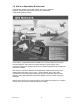
1.2 AIS in an Operational Environment This illustration depicts a typical AIS System, where two or more AIS equipped vessels (and shore based systems) are automatically communicating with each other. On the bottom, a typical NAUTICAST installation in a common environment is shown. The NAUTICAST is connected to the vessels emergency power supply, and in connection with the VHF, and GPS-Antennas, the minimal requirements for Transponder operation are fulfilled.
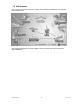
1.3 AIS Networks The scenario below shows a full AIS coverage area (including all applications and complete shore infrastructure). The Carriage Requirement currently applies to SOLAS Vessels and will be extended on Inland Waterways. Installation Manual 3 Y1-03-0212 Rev.
2 NAUTICAST 2.1 System Overview Unlike other AIS devices, the NAUTICAST combines all required functions into one cabinet. Additionally, the NAUTICAST gives the operator a number of additional features (easy mounting & installation, environmental protection and smallest dimensions). Installation Manual 4 Y1-03-0212 Rev.
3 Installation IMPORTANT: AUTHORITIES MANDATES that after the physical installation has been successfully completed, all ships data and settings be entered into the AIS transponder. See Section 4 for further instructions. 3.1 Installation Requirements General Requirements Please note that international conventions, regulations, instructions and guidelines have to be adhered to when installing the NAUTICAST.
Step-by-Step Installation Procedure: • • • • • • Mount the NAUTICAST close to ships operation workstation for traffic surveillance and maneuvering. Use the VHF adapter cable (P/N 2612) together with the VHF plug and TNC plug to connect the VHF and GPS antenna cables and antennas. The sensors, ECDIS, PC, pilot case, long range devices and auxiliary displays can be connected to the NAUTICAST cabinet by the AIS cable by means of the connection box.
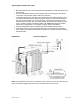
Components and Interfaces The diagram below illustrates which devices can be connected to the NAUTICAST. For a detailed description of sensor connecting e.g. an existing Gyro to the NAUTICAST refer to Chapter 3.5 “Sensor Interface Definitions.”. 3.
3.4 Interface NMEA Description: 3.4.1 Sensor - Interface CH1, CH2, CH3 Refer to Chapter 3.8 for detailed information on Sensor - Interface and Configuration. 3.4.
3.4.3 Pilot Port CH 5 The used sentence formatters for the pilot plug are the same as those listed for the ECDIS port. Note: A pilot input/output port is part of an AIS Class A installation. A plug connected to this port should be installed on the bridge near the pilot’s operating position, so that a pilot can connect a Personal Pilot Unit (PPU) if required. Also, a power connector for the pilot unit should be available nearby.
3.4.5 DGPS – DGNSS Channel 9 Field / Protocol information: All fields are provided with further information; please refer to ITU-R M.823-2 / RTCM SC 104 for detailed field information. 3.4.6 Alarm Circuit – BIIT Channel 10 The AIS requires that an alarm output (relay) must be connected to an audible alarm device or the ships alarm system, if available.
3.5 Sensor Interface Definitions All interface ports of the NAUTICAST comply with IEC-61162-1 / -2 and NMEA-0183 HS 3.0 specifications (aligned to RS422 parameters). 3.5.1 Talker drive circuits The maximum output current is Imax = 50mA on each port. The drive circuit meets the requirements of ITU-T V.11. 3.5.2 Listener Receiver Circuits Multiple listeners may be connected to a single talker. Optional termination resistors (120Ohm) for the input lines are provided in the connection box.
3.6 Sensor notes External Sensor The AIS has interfaces (configurable as IEC 61162-1 or 61162-2) for position, bottom track (BT) speed, heading and rate of turn (ROT) sensors. In general, sensors installed in compliance with other carriage requirements of SOLAS Chapter V should be connected to the AIS System.*1. The sensor information transmitted by AIS should be the same information being used for navigation of the ship.
3.7 Sensor Hardware Installation: 3.7.1 Installation of an RS422 serial interface: In most cases, the output from a GPS is already being used by existing navigation equipment. It is possible to split an RS 422 output for two devices. If the signal becomes too low, then an NMEA splitter has to be used. Example for single talk multi-listener connection: Shields A - IN B + IN G1 (or 2,3) C (GND) AIS Conncetion Box Talker (e.g.
3.8 Sensor Software Configuration 3.8.1 Introduction The NAUTICAST AIS requires a connection to various sensor devices. Sensor Configuration should enable compatibility with existing navigation devises aboard any vessel. This chapter deals with several ways to configure the NAUTICAST and to comply with the requirements of the specific sensor interfaces. Configuration and display is visible on two screens of the Sensor Configuration Menu.
After accessing the Sensor Configuration menu this main configuration screen is active: N 1^19' E 0^12' |1> N/A|2>0.00|3>0.
*********** Sensor Settings ************ ************************************** * * * Please stay... * * analyze Sensor 1..3 * * this takes max. 30sec. * * * ************************************** ---------------------------------------| | | | Back It is possible to interrupt this process by pressing the “Back” - Button [M8]. After the analysis is complete, the Transponder will list the data used for the AIS operation. N 1^18' E 0^12' |1> N/A|2>0.00|3>0.
3.8.3 Real-Time Analysis of NMEA Data Streams After these configuration procedures, an overview of the current Sensor Software Configuration has been attained. This filtered NMEA data can be analyzed further. The data source is shown on the screen below. The source can be internal or external devices, the received NMEA sentence and the channel where this data was identified (Sensor 1, 2, 3 or calculated), as well as the measured update rate. N 1^19' E 0^13' |1> N/A|2>0.00|3>0.
Each time the analysis process for sensor configuration is undertaken; a trace file (see below) is automatically generated and sent out to the ECDIS-Port. This output can also be used as a Sensor Configuration Report. $PNAUSCA,4800,4800,4800,1 $PNAUSCD,------------ Sensor Settings -----------$PNAUSCD,Date : 06/22/2004 08:57:05 $PNAUSCD,Hardware: AIS Transponder Class A $PNAUSCD,Software: 2.0.0.11R3 $PNAUSCD,SW Stamp: Jun 14 2004 11:46:10 $PNAUSCD,LAT : N 53^30.123' LON : E 10^ 1.
3.8.4 Sensor Monitoring for Problem Analysis For specific information on a particular sensor, the NMEA input data can be monitored and is listed on the AIS display. N 1^21' E 0^15' |1> N/A|2>0.00|3>0.
3.8.5 Priority Handling of Sensor Sentence This table shows the priority handling of NMEA sentences. The sentences which are treated with higher priority are listed first. Positioning System Time of Position Latitude/Longitude Position accuracy Rate of Turn(ROT) Reference Datum Speed over Ground Heading RAIM Indicator Source Priority HIGH GNS GLL GGA RMC ROT DTM VBW VTG OSD RMC HDT OSD GBS LOW 3.8.6 Supported NMEA-0183 Sentences DTM - Reference 1 2 3 4 5 6 7 8 9 | | | | | | | | | $--DTM,ccc,a,x.
4) Longitude 5) E or W (East or West) 6) GPS Quality Indicator, 0 - fix not available, 1 - GPS fix, 2 - Differential GPS fix 7) Number of satellites in view, 00 - 12 8) Horizontal Dilution of precision 9) Antenna Altitude above/below mean-sea-level (geoid) 10) Units of antenna altitude, meters 11) Geoidal separation, the difference between the WGS-84 earth ellipsoid and mean-sea-level (geoid), \-\ means mean-sea-level below ellipsoid 12) Units of geoidal separation, meters 13) Age of differential GPS data,
Used Fields: 1,2,3,4,5,6,7 1:UTC 2:Lat 3:LaInd 4:Lon 5:LoInd 6:Acc 7:Sat RMC - Minimum Navigation Information 12 1 2 3 4 5 6 7 8 9 10 11| 13 | | | | | | | | | | | | | $--RMC,hhmmss.ss,A,llll.ll,a,yyyyy.yy,a,x.x,x.x,ddmmyy,x.
9) Status, A = Data Valid 10)CRC Used Fields: 1,5,6,7,8,9 1:COG 5:SOG 6:SOGIn 7:SOG 8:SOGIn 9:Valid OSD - Ship Data 1 2 3 4 5 6 7 8 9 10 | | | | | | | | | | $--OSD,x.x,A,x.x,a,x.x,a,x.x,x.
3.8.7 Calculated Values Processed dynamic ship data such as position, SOG etc. is generated by NMEA sentences. Exceptions: If "Calc" is displayed on the sensor analyze screen, this means that this sentence is used for calculating dynamic ship data. ROT out of HDT ROT direction left / right -/+ will be calculated out of the HDT Message, if a TIROT sentence (only “TI”-Talker devices are valid) is not connected.
3.
Black BK White WH Red RD Green GN Brown BR Blue BL Orange OR Yellow YL Violet VI Gray SL(Slate) Pink PK 3.
3.11 Pin-Description Communication-Cable / Socket 50-Pins Communication-Cable / Socket ( Sub-D 50 Socket ) 1 34 18 2 35 19 3 36 20 4 37 21 5 38 22 6 39 23 7 40 24 8 41 25 9 42 26 10 43 27 11 44 28 Blue Sign - Switch Blue Sign - Switch 12 45 29 13 46 30 14 47 31 15 CH15_TxD 48 32 CH15_RxD 16 49 CH15_GND 33 17 50 CH15 Communication RS232 Spare Do not use Communication Socket (female) Installation Manual 27 Y1-03-0212 Rev.
3.12 Communication Cable RS232 (Sub-D 50 Socket) BlueSign Switch BlueSign Switch 28 44 RS232 SUB-DB9 CH15_RxD CH15_TxD CH15_gnd Installation Manual 32 15 49 Communication PC 28 3 2 5 Y1-03-0212 Rev.
3.13 Installation of VHF / GPS Antennas Interference to the Ship’s VHF Radiotelephone The AIS ship borne equipment, like any other ship borne transceiver operating in the VHF maritime band, may cause interference to a ship’s VHF radiotelephone. Because AIS is a digital system, this interference may occur as a periodic (e.g. every 20 seconds) soft clicking sound on the ship’s radiotelephone.
All outdoor connectors on the coaxial cables should be fitted with preventive isolation, such as shrink-stocking with silicone to protect the antenna cable against water penetration. Coaxial cables should be installed in separate signal cable channels/tubes, and at least 10 cm away from any power supply cables. Crossing of cables should take place at right angles (90°). Coaxial cables should not be exposed to sharp bends, which may lead to changes to the characteristic impedance of the cable.
Attenuation values Type GPS-Antenna GPS-Antenna Comb.
4 Starting the NAUTICAST 4.1 Initial Set Up of the NAUTICAST for operation ATTENTION: AUTHORITIES MANADATE THAT YOU ENTER THIS INFORMATION. After installing the antennas and hardware the following User, Voyage related and Ship Settings data needs to be entered. Upon Start-up (Applying power) enter the following information. a) Enter MMSI Number - See paragraph 4.2 on entering information. During the initial boot or after “factory settings” the user is asked to enter a valid MMSI number.
4.2 Entering the MMSI / IMO / DAC / ESN Numbers Select from the Main Menu “Service Configuration” Number 6. Menu is SERVICE password protected with default password “NAUT”. Enter Service Password and use the up and down arrows on keypad to select “Change MMSI / IMO” than press M5 “Select” or “by pressing number 3 on the keypad. Input your MMSI and IMO number and press Save to store data. Unit will reboot itself after pressing Save. Continue to 4.2 after reboot. N 1^19' E 0^13' |1>0.01|2>1.30|3>1.
N 1^21' E 0^14' |1> N/A|2>0.00|3>0.10nm ********** Change MMSI / IMO *********** MMSI :1193046 IMO No.:303174162 ---------------------------------------NUM| Save | | | Back Select Submenu 4 “Change DAC / ESN” with cursor button [Up] & [Down] by pressing Nr. 4 on the keyboard. N 1^21' E 0^14' |1>0.01|2>1.30|3>1.80nm |---------------------------------| 6. Service Configuration -----| | | +- 1. Change Service Password View | +- 2. User Password Settings | +- 3. Change MMSI / IMO -----| +- 4.
N 1^21' E 0^14' |1> N/A|2>0.00|3>0.10nm *********** Change DAC / ESN *********** DAC ESN : 200 : A123456B ---------------------------------------NUM| Save | | | Back Installation Manual 35 Y1-03-0212 Rev.
4.3 Entering Ship Settings Select from the Main Menu “Ship Settings” Menu is USER password protected with default password “NAUT”. Enter Password and use the up and down arrows to edit Ship Settings then press Enter or the numeric reference on the keypad to select and edit. Save after editing. Main Menu Example: N 1^23' E 0^16' |1>0.01|2>1.30|3>1.80nm |---------------------------------| Menu -----| | | +- 1. Messages View | +- 2. AIS Status | +- 3. Voyage Settings -----| +- 4. Ship Settings | +- 5.
Setting the Internal and External GPS Antenna Position. Note: It is critical for the proper orientation of your ship to other AIS users to enter this data accurately. Example: Length of ship = 220m and Beam = 43m. GPS ANTENNA location on ship (is x in above Menu example) is located 200 meters from bow (A) and 33 Meters from Starboard side (D). Note: You can only enter Dimension A and D. B and C are automatically calculated. You would enter A200D33 (without spaces, no decimals and no commas).
4.4 Entering Voyage Related Data Select from the Main Menu “Voyage Settings” Menu is USER password protected with default password “NAUT”. Enter Password and use the up and down arrows to edit Voyage Related data then press Enter or the numeric reference on the keypad to select and edit. Save after editing. Main Menu Example: N 1^20' E 0^13' |1> N/A|2>0.00|3>0.10nm |---------------------------------| Menu -----| | | +- 1. Messages View | +- 2. AIS Status | +- 3. Voyage Settings -----| +- 4.
Select Submenu 1 “General Settings” with cursor button [Up] & [Down] by pressing Nr. 1 on the keyboard. Scroll the Data Fields with [Enter] and input own vessel data. Enter a SOLAS draught in meter (max. = 25.5m), a Inland draught in centimetre (max. = 2000cm) and air-draught value in centimetre (max. = 4000cm) as well as the correct navigational status setting. Save the new settings by pressing [Save], and return to the Main Menu Screen by pressing [Exit].
N 1^18' E 0^12' |1>0.01|2>1.30|3>1.80nm ************* PoB Settings ************* Crew Members:0-254 (255 = unknown = default) Passenger :0-8190(8191= unknown = default) S. Personal :0-254 (255 = unknown = default) -------------------------Total :nnnn Members M6: Send addressed PoB Message M7: Broadcast PoB Message ---------------------------------------Num| Save |Addressed |Broadcast | Back Note: The total number of persons on board will b e calculated automatically.
4.5 Service and User Passwords The Transponder system is equipped with two levels of Password Protection, User and Service Password. 1) The User Password, which is the lower security level, allows access to all menus except Menu 6: Service Configuration which is protected by the Service Password. 2) The Service Password is required in order to enter the Service Configuration Menu.
Service Menu Example: N 1^21' E 0^14' |1>0.01|2>1.30|3>1.80nm |---------------------------------| 6. Service Configuration -----| | | +- 1. Change Service Password View | +- 2. User Password Settings | +- 3. Change MMSI / IMO -----| +- 4. Restore Factory Settings | Msg. | | -----| | Displ| ---------------------------------------NUM| Select->| | |<-Back Service Password Menu Example: N 1^25' E 0^18' |1>0.10|2>1.30|3>1.
N 1^21' E 0^14' |1>0.01|2>1.30|3>1.80nm |---------------------------------| 6. Service Configuration -----| | | +- 1. Change Service Password View | +- 2. User Password Settings | +- 3. Change MMSI / IMO -----| +- 4. Restore Factory Settings | Msg. | | -----| | Displ| ---------------------------------------NUM| Select->| | |<-Back Select Submenu 1 “Change User Password” with cursor button [Up] & [Down] by pressing Number 1 on the keyboard. N 1^21' E 0^14' |1>0.01|2>1.30|3>1.
5 Troubleshooting 5.1 Reading and understanding Alarms: The NAUTICAST differentiates between Alarm and TXT messages. An Alarm informs the user about major system malfunctions and failings in the connected sensors. The Alarm Status informs the user about all active Alarms. The Alarm will be disabled and deleted from the Alarm Status, as soon as the displayed problem has been rectified. The TXT status displays additional sensor information and the UTC clock status. See tables (Section 5.2 and 5.
5.2 Alarm Codes ID Description Text 01 AIS: Tx malfunction 02 03 04 05 AIS: Antenna VSWR exceeds limit (VSWR - Voltage Standing Wave Ratio) AIS: Rx channel 1 malfunction AIS; Rx channel 2 malfunction AIS: Rx channel 70 malfunction Cause/Source VHF Antenna, cabling VHF antenna, installation Reaction: The transponder unit continues transmission. Remedy: Check the antenna and the antenna cabling (RG214 / 50 Ohm cable required).
53 AIS: BATTERY SOON LOW Battery is soon out Reaction: Own ship data is lost after powering on/off the system. Remedy: consider to contact Technical Support for additional help of capacity Conditions for AIS: PRESS ENTER TO enabling 1 Watt 55 EXIT 1W/AUTO TX TX power are not MODE valid 56 AIS: ENTER MMSI NUMBER No valid MMSI entered. Reaction: Conditions for enabling 1 Watt TX power are not valid.
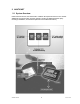
6 Accessories The following material is included with the NAUTICAST. NAUTICAST Inland AIS Kit includes 1 NAUTICAST Inland AIS Transponder 1 installation manual, 1 user Manual 3 caps of plug 1 cable clamp (M5 thread) 1 guide plate Kit 3 angles + 3 mounting screws (screw bolt + square nut) The NAUTICAST Inland AIS is supplied with some of the components listed below (contents depend on customer requirements).
7 Technical Information PHYSICAL Size in mm / inch (w) Size in mm / inch (h) Size in mm / inch (d) Weight Operating Temperature 281,26mm / 11,07inch 60mm / 2,36inch 201,26mm / 7,92inch 2490g / 5,50pound -15°C to +55°C / 5°F to 131°F POWER SUPPLY Supply Voltage (galvanic isolated) Input Current 24 V DC (-10% +30%) min.7 A (24V) INTERFACES Number of Data Ports IEC 61162-1/2 ITU-R M.823-2 Bitrate CH1 Sensor Input; (i.E.: GPS) CH2 Sensor Input; (i.E.: GYRO) CH3 Sensor Input; (i.E.
8 Contact and Support Information Contact your local dealer for NAUTICAST support. Please see our ACR Website for Service Listing. ACR Electronics Europe GmbH Mariahilfer Straße 50/2/11 A-1070 Vienna, Austria Tel: +43 (1) 5 237 237 - 0 Fax: +43 (1) 5 237 237 - 150 Email: Technical.Support@acr-europe.com Web: www.acr-europe.com ACR Electronics Customer Service 5757 Ravenswood Road Fort Lauderdale, FL 33312, U.S.A. Tel.: +1 (954) 981-3333 Fax: +1 (954) 983-5087 Email: info@acrelectronics.com Web: www.
9 Appendix 9.1 Samples for battery calculation 9.1.1 Typical Installation GMDSS Battery size calculation for 1 hour (Battery size calculation based on the IMO regulations Chapter IV - Reg.13) Ship Name Battery capacity Battery Type QMIII 230Ah 2x (12V / 135) Area A1, A2, A3 Battery located in battery chest on observation deck Pos Qty. Equipment I-max I-standby Total (A) (A) (A) (I-max/2 + I-standby )*Qty.
9.1.2 RM GMDSS Compact-Console Area A3 with 250 W MF/HF GMDSS Reserve Battery Calculation ( 24 V DC ) for Raytheon Marine GmbH GMDSS Compact-Console Area A3 with 250 W MF/HF According to IMO Regulation COMSAR/Circ.16 4. March 1998 A: with Emergency Generator (SOLAS IV 13.2 ) The GMDSS equipment shall be able to operate one (1) hour on reserve power with 50% of time in transmission mode and 50% in receiving mode. B: without Emergency Generator (SOLAS IV 13.
Case A: 1h x ( 0.5 I TX + I RX + I Add ) x 1.4 = 44.06 Ah recommend battery capacity is 86 Ah Charger: I Charg x 0.1 I Batt/h = 8.6 A recommend charger is type 20 A Case B: 6h x ( 0.5 I TX + I RX + I Add ) x 1.4 = 264.39 Ah The battery calculation should not be used for uninterruptible power supply (UPS) configuration 9.
Source, Draw.-No.
EG - Konformitätserklärung CE - Declaration of Conformity Diese Konformitätserklärung bestätigt, dass das unten benannte Produkt den Auflagen der EC Council Directive 96/98/EC vom 20 Dezember 1996 für maritime Ausrüstung, geändert durch die EC Council Directive 2002/75/EC vom 2. September 2002 entspricht und von der benannten Stelle Nr. 0735 (BSH) typengeprüft. Darüber ist die Konformität zum Standard „Vessel Tracking and Tracing Standard for Inland Navigation Edition 1.0“ vom 31.5.2006 gewährleistet.
Konformitätserklärung Declaration of Conformity Diese Konformitätserklärung bestätigt, dass das unten benannte Zubehör gleich oder besser dem im untenstehenden Zertifikat ausgewiesenen Zubehör ist. This declaration of conformity certifies that the mentioned accessory is equal or better to the equipment stated in the beyond Certificate.
Konformitätserklärung Declaration of Conformity Diese Konformitätserklärung bestätigt, dass das unten benannte Zubehör gleich oder besser dem im untenstehenden Zertifikat ausgewiesenen Zubehör ist. This declaration of conformity certifies that the mentioned accessory is equal or better to the equipment stated in the beyond Certificate.
Konformitätserklärung Declaration of Conformity Diese Konformitätserklärung bestätigt, dass das unten benannte Zubehör gleich oder besser dem im untenstehenden Zertifikat ausgewiesenen Zubehör ist. This declaration of conformity certifies that the mentioned accessory is equal or better to the equipment stated in the beyond Certificate.
Konformitätserklärung Declaration of Conformity Diese Konformitätserklärung bestätigt, dass das unten benannte Zubehör gleich oder besser dem im untenstehenden Zertifikat ausgewiesenen Zubehör ist. This declaration of conformity certifies that the mentioned accessory is equal or better to the equipment stated in the beyond Certificate.
Quick Replacement Guide 1. Prepare the following tools: Screwdrivers, spanners User Password: your personal password (factory default setting is ‘NAUT’) 2. Read out your Transponder configuration Steps to do this: Press Menu Press 2 2.AIS Status Press 2 2.Own Ship Data Write down the current configuration settings here: IMO No. : Dest : ShipName : EAT : ShipType : MMSI : Length : CS : Cargo : Beam : Draught : Press Menu Press 4 Password [UserPassword] [Enter 4.
6. Connect cables 6.1. AIS-Cable to screw on 6.2. VHF/GPS Cable to screw on 7. Mount the replacement unit 7.1. Bracket Mounting 7.2. Frame Mounting 8. Key in the configuration settings from above: Following steps to key in the Configuration Press Menu Press 6 Password NAUT [Enter Press 3 6.Service Configuration ] (Default Factory Password) 3.