Please read this first! Warning: Although ACR strives for accuracy in all its publications; this material may contain errors or omissions, and is subject to change without prior notice. ACR shall not be made liable for any specific, indirect, incidental or consequential damages as a result of its use. ACR components may only be used in safety of life devices or systems, with the express written approval of ACR, as the failure of such components could cause the failure of the ACR device or system.
NAUTICAST Transponder User Manual Index 1 STARTING THE NAUTICAST ............................................................................................... 5 1.1 1.2 1.3 1.4 1.5 2 3.1.1 3.1.2 3.1.3 3.1.4 3.2 3.3 3.4 3.4.1 3.4.2 3.4.3 3.4.4 3.4.5 3.4.6 3.4.7 3.4.8 3.5 3.5.1 3.5.2 3.5.3 3.5.4 3.5.5 3.5.6 3.5.7 3.6 3.6.1 3.6.2 3.6.3 3.6.4 3.6.5 Navigation Screen...........................................................................................................................................
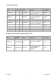
History of Changes Date 2002-12-04 Version 1.0 2003-03-18 1.0 2003-03-27 1.0 2003-03-31 1.0 2003-06-30 2004-06-03 1.0.1 1.0.2 2004-07-30 1.0.3 2005-07-30 1.0.4 2005-11-21 2006-05-23 2006-11-06 2009-07-28 1.0.5 1.0.6 1.0.7 1.0.8 Rev. Status A Released B Released C D Comments Latest release amendments Updated EC-Conformity Document inserted. B553 picture update New front cover.
1 Starting the NAUTICAST 1.1 Initial Set Up of the NAUTICAST for operation ATTENTION: IMO REGULATIONS MANDATE THAT YOU ENTER THIS INFORMATION. After installing the antennas and hardware the following User, Voyage related and Ship Settings data needs to be entered. Upon Start-up (Applying power) enter the following information. a) Enter MMSI Number - See section 1.2 on entering information. During the initial boot or after “factory settings” the user is asked to enter a valid MMSI number.
1.2 Entering the MMSI and IMO Numbers Select from the Main Menu “Service Configuration” Number 6. Menu is SERVICE password protected (Please see Appendix 7.2 for password information). Enter Service Password and use the up and down arrows on keypad to select “Change MMSI / IMO” than press M5 “Select” or “by pressing number 3 on the keypad. Input your MMSI and IMO number and press Save to store data. Unit will reboot itself after pressing Save. Continue to 4.
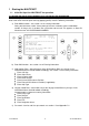
1.3 Entering Ship Settings Select from the Main Menu “Ship Settings” Menu is USER password protected (Please see Appendix 7.2 for password information).Enter Password and use the up and down arrows to edit Ship Settings then press Enter or the numeric reference on the keypad to select and edit. Save after editing. Main Menu Example: N 1o23' E 0o16' |1>0.01|2>1.30|3>1.80nm |---------------------------------| Menu -----| | | +- 1. Messages View | +- 2. AIS Status | +- 3. Voyage Settings -----| +- 4.
GPS ANTENNA location on ship (is x in above Menu example) is located 200 meters from bow (A) and 33 Meters from Starboard side (D). Note: When only using internal GPS antenna it is ok to have default values for external position since they are not used. Ref.Points ext (Position of the external GPS antenna) A = 200m the distance from bow (front) to the antenna.
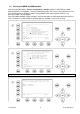
N 1o31' E 0o24' |1>0.01|2>1.30|3>1.80nm ---------------------------------------++++++++++++++++++++++++++++++++++++++++ User password protected! Please enter user password: ++++++++++++++++++++++++++++++++++++++++ ---------------------------------------| Enter | | | Exit Scroll to the Voyage Setting Fields with up and down arrows and input your vessel data. Select a default Cargo Type, Draught, POB (Persons on board), Destination, ETA and Navigation Status Setting using the [Left] & [Right] arrow keys.
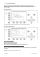
Changing the Service Password Select “Service Configuration” from the Main Menu with the cursor button [Up] & [Down] or press Number 6 on the keyboard. The password query field appears. Input default Service Password and press M5 [Enter].
Service Password Menu Example: N48^12' E 16^26' |1> N/A|2> N/A|3> N/An ******* Change Service Password ******* Enter new password : Repeat new password: {Length: 6..8 characters --------------------------------------| Enter | | | Back Enter the new Password: Then push Enter (M5). Repeat the new Password: Then Push Enter (M5). A minimum of 6, a maximum of 8 characters are allowed. Should the new password include numbers, use the shift key to generate them. Press Save to store the change.
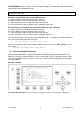
N48^12' E 16^26' |1> N/A|2> N/A|3> N/Anm |---------------------------------| 6-2. User Password Settings -----| | | +- 1. Change User Password View | +- 2. Change Password Protection | -----| | Msg. | | -----| | Displ| ---------------------------------------NUM|Select->| | |<-Back Enter the new Password. A minimum of 6, a maximum of 8 characters are allowed. Should the new password include numbers, use the shift key to generate them. Repeat the new Password.
2 NAUTICAST User Interface Display Safety Keys Soft Keys [M1] – [M8] Navigation Screen Header (max. 3 lines) _________________ Navigation Screen or MENU Structure (Content 13 lines) Keyboard Enter Key User Manual 13 Cursor Cross Y1-03-0203 Rev.
2.1 NAUTICAST Keyboard The NAUTICAST is fitted with a full alphanumeric keyboard, with the following functions: By pressing any key on the keyboard the letters are addressed. Number symbols and special characters are addressed by holding down the shift [] key and simultaneously pressing the chosen key. The characters ($; %; &; /; (; ); <; and pressing the chosen key. 2.
2.4 Explanation of the Soft Keys The Soft Keys are divided into vertical static keys [M1-M4] and horizontal dynamic keys [M5-M8], which differ in function according to the current application. Soft Key Definition filter option on AIS targets in graphical view FA (hides received Class A targets) FB (hides received Class B targets) [M1] Display Modes [M2] This Soft Key allows toggling between the different Display Modes. Safety Message [M3]: This Soft Key allows direct Message Writing.
3 NAUTICAST Screens The advanced version of the NAUTICAST offers three display modes: Navigation Screen - Standard screen, automatically visible Menu Structure - Visible after pressing the [Menu] Soft Key Graphical User Interface - The Graphical User Interface is visible after pressing the [M2] Soft Key (new mode) 3.1 Navigation Screen This screen provides the user with Navigation Data from their own vessel and lists all other vessels within receiving range.
3.1.1 Own Vessel Data LAT:N LON:E 1°27.845'ExtSOG:34.6kn 0°21.289'ExtCOG:173.0° 05/26/06 10:52:26 LAT: Latitude LON: Longitude Date: The actual UTC - date (MM.DD.YY) and time (hh.mm.ss) are displayed on the top right hand corner of this view. IntGPS: 3D IntGPS A/ ExtHDT:222° Reg6 Indicates normal or differential mode of GPS position. 2D or 3D: Indicates the precision of the GPS result. Indicates the used position source: intGPS.
3.1.2 Other Vessel Data 001/021..SHIPNAME....RNG.BRG..SOG..COG.. 001/021 (E.g: Vessel 01 of 021) current or selected Vessel/ Total number of Vessels (max. 256 Vessels) ShipName: Name of the Ship and AIS – Type: Cl-A: SOLAS Class-A Ship Cl-B: Leisure Craft Base: Base station SAR : Search and Rescue Aircraft RNG Vessel Range Note: The vessel closest to own ship, or where position data is unknown (N/A), is listed first.
3.1.4 Other Vessel Details This screen shows the Dynamic, Voyage and Vessel Related Data, which is currently being transmitted by a previously selected vessel. N 1o21' E 0o14' |1>0,10|2>1.30|3>1.80nm Time 2:07 -----------------POS:001/021 LAT : S 74o 50.231' LON :W o 9o 34.192' Heading :77o ROT :-0.2 /min l IMO No. :90733283 MMSI:5004 ShipName:DOREEN CS:DORET6W ShipType:Passenger ship Length :310m Beam:73m RefPoint:A190 B120 C10 D>=63m Cargo :N/A or harmless Draught :3.3m Dest.
Reference Point (in meters): This information indicates the Reference Point of the used GPS Antenna onboard the vessel. RefPoint:A190 B120 C10 D<63m A: B: C: D: 190m 120m 10m <63m (means more than 63m in the case of a very large vessel) Vessels Cargo: Indicates the type of cargo on board. N/A or harmless Further Vessel Details: Draught : 3.
3.2 Menu Structure To call up the Main Menu, press the [Menu] button once, and all Submenus are displayed. The cursor position indicates the selected submenu. Menu navigation is achieved by pressing the [Up] or [Down] keys to select, and then by pressing [Enter] to confirm the desired Submenu selection. To escape from any Submenu and returning to the Navigation Screen, press the [M2] button at any time. The own vessel‟s current Navigation Information is continuously displayed on the first line.
3.4 Sub-Menus Overview 3.4.1 Messages N 1o19' E 0o12' |1>0.10|2>1.30|3>1.80nm | 1. Messages -----| | | +- 1. Write Addressed SRM View | +- 2. Write Broadcast SRM | +- 3. Lock Request | +- 4. Inbox History -----| +- 5. Inbox SRM | +- 6. Inbox LRI Msg. | +- 7. Inbox Lock Reply | +- 8. Interrogate IFM -----| | Displ| ---------------------------------------NUM|Select->| | | <-Back 3.4.2 AIS Status N 1o18' E 0o12' |1> N/A|2>0.00|3>0.10nm |---------------------------------| 2. AIS Status -----| | | +- 1.
3.4.4 Ship Settings – (User Password Protected) N48^12' E 16^26' |1> N/A|2> N/A|3> N/Anm ************ Ship Settings ************* Call Sign:OEZ1234 /\ + ShipName :SOLAS 55 / \| Ref.Points ext int | | A: 200m 220m | A B: 20m N/A | | C: 10m 10m | +--| D: 33m 33m | | B Len (A+B): 220m 220m | | | Beam(C+D): 43m 43m +-C-+D-+ Ship Type: >>> DATA OK. PRESS M5 TO SAVE DATA <<< ---------------------------------------| Save | | | Back 3.4.
Display Settings N 1o21' E 0o15' |1>0.10|2>1.30|3>1.80nm *********** Display Settings *********** Mode | +-[*] Day Min Max | +---- Brightness:<9> [*********] | +---- Contrast : 6 [****** ] | | +-[ ] Night Min Max +---- Brightness: 3 [*** ] +---- Contrast : 2 [** ] ---------------------------------------NUM|DayNight| | | Back 3.4.7 Graphical Display Settings N 1o46' E 0o39' |1>0.10|2>1.30|3>1.80nm |---------------------------------| 8 Graphical Display Settings -----| | | +- 1.
Dynamic Keys: Messages [M5] [Select] Select chosen Submenu [Enter] Confirm Message Submenu Selection [M8] [Back] Return to Main Menu [Up] / [Down] Screen Navigate Submenu for Selection Writing Messages: This screen provides a means to write and send messages. It is possible to select between an Addressed Message to a single selected vessel, and a Broadcast Message, which is sent out to all vessels in the current Vessel Listing.
Dynamic Keys: Messages [M5] [Select] Write Message to Selected Vessel [M8] [Back] Return to Messages Menu [Enter] Write Message to Selected Vessel b) Using the NAUTICAST Message Editor After selecting a vessel, the Message Editor is automatically displayed. Messages containing a maximum of 156 characters are allowed. Longer texts require a second message. After text input completion, transmission to the selected addressee is facilitated by pressing the [Send] button.
c) Confirmation of Sent Addressed Message The confirmation screen shows the successful message transmission and indicates which channels (AIS1 or AIS2) were used. Successful Message Transmission on Channel AIS1: LAT:N 1oo18.963'ExtSOG:34.6kn 05/21/2006 LON:E 0 12.408'ExtCOG:173.
It is possible, that the recipient‟s Transponder could not receive the message at all, and in this case the following screen is displayed. It is then recommended to resend the message. Unsuccessful Message Confirmation (no acknowledgement) N 1o19' E 0o12' |1>0.10|2>1.30|3>1.
e) Confirmation of Broadcast Sent Message This Confirmation Screen shows that the message was successfully transmitted on the Broadcast Setting. By pressing [Back] the user automatically returns to the Message Editor for further Messaging. The [SendTo] returns the user to the Vessel Listing, with the option of further Message Writing to individual vessels. N 1o19' E 0o13' |1>0.10|2>1.30|3>1.
f) Long Range Interrogation Mobile, and shore-based stations have the ability to interrogate vessels and make requests for information over the “Long Range Interface”. The interrogated vessel can either reply in automatic, or in manual mode. The interrogation request is displayed in both modes. The arrival of a Long Range Interrogation Request is indicated by: 1L on the top right hand corner of the Navigation Screen. The LRI automatically arrives in the Message Inbox LRI and can be handled from there.
An LRI has arrived; The NAUTICAST Settings are configured to Automatic Mode: N 1o20' E 0o13' |1>0.10|2>1.
N 1o20' E 0o14' ||1>0.10|2>1.
Inbox History: Overview of Received Messages and Alarms Message Types: Description ASRM Addressed Safety Related Message BSRM Broadcast Safety Related Message ALR Alarms (Details – see Alarm Types chapter 5.
ASRM 13:43 PIRATE ATTACK! 5264 Addressed Safety Related Message, acknowledged by recipient, arrived at 13:43, with text “Pirate Attack”, from vessel with MMSI 5264 ASRM*13:42 HIGH WINDS IN AREA! 5004 Addressed Safety Related Message, unacknowledged by recipient, arrived at 13:42, with text “High winds in area!” from vessel with MMSI number 5004 ALR 13:40 external EPFS lost 25 Alarm, no longer active (revoked) with ID Number 25 (see Alarm Types), revoked at 13:40 with text “external EPFS lost” ALR!*13:38 g
ASRM: Information Time 17:39 Date 11/26 (mm.
3.5.2 AIS Status The AIS Status Menu provides a variety of information concerning own vessel settings, as well as the current AIS status of the other vessels, which are displayed in the Vessel Listing. Version Info provides details of the actual software release currently installed. Security Log traces the downtimes of the Transponder, to ensure those periods of down time when the transponder is out of order or lacking electricity can be traced. N 1o19' E 0o12' |1> N/A|2>0.00|3>0.
Mod.: AIS Transmission Mode AU Autonomous AS Assigned IN Interrogation/Polled Mode ?? Unknown Used Channel AIS1, AIS2 Syn.: (UTC source) D UTC direct I UTC indirect B Sync to Base A Sync to mobile with the most received stations (Semaphore) RXVe: Total number of all received stations by the individual vessel. MMSI: MMSI number of the individual vessel.
Own Vessel Position: LAT : N 1°18.901' LON : E 0°12.345' Heading and Rotation of own vessel: Heading :77o ROT : +5.4° IMO-Number and MMSI of own vessel: IMO No. : 9100254 MMSI: 257530700 Name and CallSign of own vessel: ShipName: MYLADY CS: D11233 Vessel Type: Pilot vessel Length and Beam of own vessel: Length:310m Beam:73m Reference Point (in meters): This information indicates the Reference Point of the used GPS Antenna onboard the vessel.
c) Version Info This Screen shows the actual Software Release which is being run on the NAUTICAST. N48^12' E 16^26' |1> N/A|2> N/A|3>0.00nm ************* Version Info ************* ## # # #### # # # # # ### # # # ## # # # ### ### # # # # ### # # ### # # # # ## # # #### # # # # # # ### ## # # #### ## # ## # # # ### # Hardware: AIS Transponder Class A R4 J Software: 2.0.S105.X309 SW Stamp: Mar 25 2009 09:45:59 Modem HW: Issue J SeCo: 0 Modem SW: 01.10.
3.5.3 Voyage Settings (User Password Protected) NOTE: The default password from the factory is mentioned on your AIS display at the protection foil. (see Appendix 0 for password information).! Before entering Voyage Related Data for initial NAUTICAST operation, it is advised to configure the User Password in: Menu 5: Configuration Submenu 1: Change User Password N 1o31' E 0o24' |1>0.10|2>1.30|3>1.
Voyage Settings Entries After a new User Password has been set, Voyage Settings may be input. A selection is made with the cursor buttons [Up] or [Down] to reach the individual input fields. The categories “Cargo” and “NavStat” are equipped with default settings, which can be selected by pressing the [Left] or [Right] buttons. Note: ETA is input in the following format: MMDDHHMM The Cargo Categories are defined by the IMO (ITU-R M.
Data Input Modes Voyage Setting Description Input Modus Cargo Cargo Category Default Setting N/A or harmless DG, HS or MP (category A) DG, HS or MP (category B) DG, HS or MP (category C) DG, HS or MP (category D) Draught Maximum present static draught Manual input PoB Number of persons on board Manual input Dest Destination Manual input ETA Estimated Time of Arrival (ETA) Manual input Navigational Status Default Setting Under way using engine, At anchor, Not under
3.5.4 Ship Settings (User Password Protected) After a new User Password has been set, the Ship Settings may be input. The Ship Settings are usually only set once, upon NAUTICAST initial operation. A selection is made with the cursor buttons [Up] or [Down] for input field selection. The category “ShipType” is equipped with default settings, which can be selected by pressing the [Left] or [Right] buttons. NOTE: The default password from the factory is mentioned on your AIS display at the protection foil.
Input Modes for Ship Settings Ships Setting Description Input Modus Call Sign Ships Call Sign Manual input Ship Name Ships Name Manual input Length Length of ship Manual input Beam Ship‟s Beam Manual input RefPntExt: Position reference points for external positioning device (GPS antenna) Manual input RefPntInt: Position reference points for GPS antenna Manual input Ship Type Ship Type according to IMO Regulations: Default Setting N/A or no ship WIG Vessel Vessel-Fishing Ve
After the Ship Settings have been input and saved, this screen appears. [Exit] takes the user back to the Main Menu. N 1o30' E 0o24' |1>0.10|2>1.30|3>1.80nm ---------------------------------------- ++++++++++++++++++++++++++++++++++++++++ Data saved.
Sample: Display: CallSign = D11233 ShipName = M/V TUGELA Length = 200m Beam = 30m RefPointExt = A170 B30 C15 D15m (location of the external GPS antenna) RefPointInT = A171 B29 C0 D30m (location of the internal GPS antenna) ShipType = Tug Setting of the external GPS antenna position: A = 170m the distance from bow to the antenna B= 30m the distance from the antenna to the stern C = 15m the distance from the port side to the antenna D = 15m the distance from the antenna to the starboard side Move with Up/down
N48^12' E 16^26' |1> N/A|2> N/A|3> N/Anm ************ Ship Settings ************* Call Sign:SO52 /\ + ShipName :SOLAS 52 / \| Ref.Points ext int | | A: 170m 171m | A B: 30m 29m | | C: 15m N/A | +--| D: 15m 30m | | B Len (A+B): 200m 200m | | | Beam(C+D): 30m 30m +-C-+D-+ Ship Type: N/A or no ship >>> DATA OK. PRESS M5 TO SAVE DATA <<< ---------------------------------------NUM| Save | | | Back | Save Back | | | 3.5.
Accessing the Configuration Menu with the default User Password N 1o18' E 0o12' |1>0.10|2>1.30|3>1.
a) Change User Password (for initial NAUTICAST Operation) It is strongly recommended to change the default User Password upon initial NAUTICAST operation. A minimum of 6, a maximum of 8 characters are allowed. Should the new password include numbers, use the shift key to generate them. N 1o19' E 0o12' |1>0.10|2>1.30|3>1.80nm |---------------------------------| 5. Configuration -----| | | +- 1. Change User Password View | +- 2. Region Settings | +- 3. Alarm Settings -----| +- 4.
This screen appears if the new User Passwords are mismatched - i.e. the New User Password and the Repeated New User Password are not identical. In this case, it is possible to re-input both the New and Repeated User Passwords again. [Exit] takes the user back to the User Password Input Screen. N 1o19' E 0o13' |1>0.10|2>1.30|3>1.
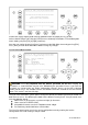
b) Region Settings A Region is a defined area, with specific VHF parameters, which are sent out by Vessel Traffic Service Stations (VTS), and received via Digital Selective Calling (DSC) or AIS. The screen shows a list of Regions, and their input sources. When the vessel enters into one of the pre-defined Regions, the NAUTICAST automatically switches to the relevant Region Setting. If a Region Number is vacant, then the relevant Region Name Slot is currently unoccupied.
Creating a New Region Parameters for setting up a new Region can be entered and saved here. N 1o19' E 0o12' |1>0.10|2>1.30|3>1.80nm ********** Create New Region *********** NE LAT(1):N 0oo 0.0000' +----------1 NE LON(1):E 0o 0.0000' | +------+ | SW LAT(2):N 0o 0.0000' | | | | SW LON(2):E 0 0.
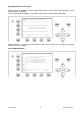
c) Alarm Settings This screen allows the user to enable or disable the generation and display of Alarms. Alarms are displayed in the Alarm Inbox (see Menu 5: Transponder Configuration, Submenu 3: Alarm Settings) and on the ECDIS screen. Note: It is highly recommended to enable the Alarm Function. N 1o19' E 0o12' |1>0.10|2>1.30|3>1.80nm ************ Alarm Settings ************ on/off Alarm generation: [*]/[ ] Note: This setting also affects output on ECDIS port.
Dynamic Keys: LR Interrogation Settings [M5] [Save] Save LRI Settings [Up] / [Down] Select Data Field for Configuration [M6] [Change] Enable or Disable selected Field for Interrogation [Enter] Select Data Field for Configuration [M7] [All On] Configure All Data [Left] / [Right] for Interrogation Enable or Disable selected Field for Interrogation [M8] [Back] Return to Menu Configuration Replying to a Long Range Interrogation Request: The arrival of an LRI is shown in the Navigation Screen (
Dynamic Keys: Replying to a LR Interrogation [M5] [OK] [M7] [Reply] Notifies User of current interrogation Display Message Editor for LRI Reply [M8] [Back] Return to Vessel Listing Sensor Settings The screen provides the means to switch the sensor speeds. It allows the user to change sensor interfaces from IEC61162-1 to IEC61162-2 settings. The data input fields are fitted with default values.
Use this menu to set up the data speed 4800/9600/38400 baud. NOTE: This Configuration should be done from advanced user like installation technicians only. Therefore you will find more details in the installation manual. During the configuration process, the NAUTICAST is not operational. GPS Settings (Service Password protected) GPS Module: The screen provides means to switch the GPS Module between the „<µBlox>‟ or „‟. You can force the AIS to search again for the GPS Module installed.
3.5.6 Service Configuration (Service Password Protected) The Service Configuration Menu allows initial configuration of the Service Password, Password Settings (on/off), MMSI/IMO Numbers and the option of resetting the NAUTICAST to Factory Settings. The Service Password is required in order to enter the Service Configuration Menu.
a) Change Service Password This screen provides a means to individually configure the Service Password. This password differs from the User Password as it allows the user access to the Menu „Service Configuration“. A minimum of 6, a maximum of 8 characters are allowed. Should the new password include numbers, use the shift key to generate them. The process of configuring the Service Password is identical to that of User Password configuration (see Menu 5: Configuration, Submenu 1: Change User Password).
b) User Password Settings N 1o24' E 0o18' |1>0.10|2>1.30|3>1.80nm |---------------------------------| 6-2. User Password Settings -----| | | +- 1. Change User Password View | +- 2. Change Password Protection | -----| | Msg. | | -----| | Displ| ---------------------------------------NUM| Select->| | |<-Back Change User Password Protection: This function allows the user to enable or disable the User Password Query Function.
c) Changing the MMSI / IMO Numbers This screen provides a means to change the MMSI and IMO Numbers; the input fields are limited to a maximum of 9 characters. N 1o19' E 0o13' |1>0.10|2>1.30|3>1.80nm ********** Change MMSI / IMO *********** MMSI :1193046 IMO No.
After pressing [OK], the Data Saved Screen confirms the Restore Factory Settings command. N 1o20' E 0o13' |1>0.10|2>1.30|3>1.80nm ---------------------------------------- ++++++++++++++++++++++++++++++++++++++++ Data saved. ++++++++++++++++++++++++++++++++++++++++ ---------------------------------------| | | |<- Exit Note: The NAUTICAST has been restored to the Factory Settings! Now please configure your: - Ship Settings Voyage Settings User Password Service Password 3.5.
Dynamic Keys: Display Settings [M5] [DayNight] or Night Settings [Enter] Switch between Day or Night Settings [M8] [Back] [Up] / [Down] Navigate Input Fields [Left] / [Right] Regulate Modes (min/max) Switch between Day Return to Main Menu NOTE: The Brightness and Contrast Setting can be directly changed from the keyboard by inputting the desired value. 3.6 Graphical User Interface (GUI) The advanced version of the NAUTICAST is fitted with the new Graphical User Interface.
Dynamic Keys: graphical user interface [M1] filter option on AIS targets in graphical view [M2] [M3] [M5] [M7] [Menu] [FN] + [Up] / [Down] [Shift]+ [Up] / [Down] / FA (hides received Class A targets) FB (hides received Class B targets) Switch between the views from the Navigation Screen press the button the 1st time will lead you to the Radar View press it the 2nd time will lead you to the Fairway View press it the 3rd time will bring you back to Navigation Screen Show alarm windows Acknowledge alarms or
pressing [M2] leads to Radar View pressing [M2] leads to Fairway View pressing [M2] leads you back to Navigation Screen User Manual 64 Y1-03-0203 Rev.
3.6.2 The Radar View This screen provides the user with a commonly used way of representing ship objects on an electronic device. The Radar View is northern orientated, as indicated by the compass on the very right top of the screen. Other AIS targets Own ship position Distance rings around the own position The Elements of the Radar View: Own Ship: A symbol for the own ship is displayed in the middle of the screen.
Dynamic Keys: Radar View [M1] Set filter option on AIS Targets [M2] Switch between the views [M3] Show alarm window [M5] Acknowledge alarms or safety related messages (SRM) [M7] Acknowledge SRM and reply [Menu] Selects the Main Menu [Up] / [Down] / Activate the minimized radar view [Left] / [Right] [FN] + Change the zoom level [Up] / [Down] [Shift]+ Scroll the view (only available in radar view) [Up] / [Down] / Zoom Levels To adjust the Radar View following zoom levels are implemented (default is zoom leve
Scrolling Since the outer distance ring does not completely fit into the (rectangle) display, it is possible to scroll the view from North or South. The maximum scrolling distance is limited to the radius of the outer distance ring in the current zoom level. The view can be scrolled by 2 steps in each direction. The view can be scrolled by pressing [Shift] + [Up] to scroll towards North and [Shift] + [Down] to scroll towards South This screen shows a 1 step scrolling in a northern direction.
The Minimized Radar View The minimized radar view shows a split screen. On the left hand side a Ship List is displayed, on the right hand side a minimized view of the Radar View is visible. This view will be displayed, if one of the cursor keys is pressed. The difference between the minimized, and the large view options are that the minimized view shows the maximum in both North and South direction, since scrolling is NOT possible.
Ship Details If a target is selected by pressing [Enter], whether in the Ship List or directly in the graphical view, the corresponding ship details are displayed instead of the minimized view. Pressing [Up] or [Down] scrolls the ship detail list by line, [Left] or [Right] by page. [M8] returns to the minimized view. 3.6.3 The Fairway View The Fairway View shows the course over ground (COG) orientated view of the Information screen data.
The Elements in the Fairway View: Compass: Shows the current COG. Fairway Lines: The Fairway Lines are border lines of a virtual fairway oriented on the actual course over ground. AIS-Targets: Other AIS targets received via VHF are displayed, if their distance is within the range of the current zoom level. Own Ship: A symbol for the own ship is displayed in the middle of the screen and can not be changed. Horizontal Lines: The horizontal lines are the equivalent to the radar views distance rings.
Zoom Level 2 would look like this: The Minimized Fairway View The minimized Fairway View shows a split screen. On the left hand side a Ship List is displayed and on the right hand side a minimized Fairway View is seen. This view is displayed, if one of the cursor keys is pressed. Fairway View [Up] | [Down] | [Left] | [Right] Minimized Fairway View Minimized View Ship List [M4] “Message Write” Button User Manual [M6] Ship List / Minimized View Switch 71 [M8] Exit Button Y1-03-0203 Rev.
The Elements in the Minimized Fairway View: “Message Write” Button: By pressing the [M4] button, a message could be sent to that AIS-Target that is currently selected in the Ship List. Ship List: This list shows the same targets as shown in the Navigation Screen. Ship List / Minimized View Switch: This switch indicates whether targets can be selected from the Ship List or from the minimized view.
3.6.4 Message and Alarm Handling Alarms If an alarm occurs, the symbol to the right of the [M3] button becomes visible. M3 Alarm Icon Pressing the [M3] button shows the details of the selected alert. Pressing [M5] leads to alarm acknowledgement and the closure of the window as well as the alarm icon disappearing. An alarm could occur at every time so the alarm icon can be seen in every view (in the big views as well as minimized views and ship details list).
3.6.5 Configuration of the Graphical Display General The configuration of the Graphical Display could be accessed over the entry point 8 of the Main Menu. N 1o46' E 0o39' |1>0.10|2>1.30|3>1.80nm |---------------------------------| Menu -----| | | +- 1. Messages View | +- 2. AIS Status | +- 3. Voyage Settings -----| +- 4. Ship Settings | +- 5. Transponder Configuration Msg. | +- 6. Service Configuration | +- 7.
Inside the Graphical Display Setting you can choose out of 4 different Sub-Menus. N 1o46' E 0o39' |1>0.10|2>1.30|3>1.80nm |---------------------------------| 8 Graphical Display Settings -----| | | +- 1. Fairway View Scale View | +- 2. Fairway View Symbols | +- 3. Radar View Symbols -----| +- 4. Other graphical Settings | Msg.
Parameter description: Parameter Angle(A) Dim(B) Dim(C) Dim(D) Description The angle α defines the visible sector. Value range: 2° to 178° The parameter Dim(B) defines the width of the fairway in percent of the horizontal line. Please ensure that Dim(C) has to be greater or equal to Dim(B). Value range: 10% to 100% The parameter Dim(C) defines the width of the fairway in percent of the „Zero-line“ (the horizontal line of the own ship position).
The following drawing illustrates the parameters from the Fairway View Scale Menu and additionally presents the transformation process from the Radar View to the Fairway View. 260° 325.0° 30° DIM(B) 15 nm 10 nm f1 f2 Horizontal line f '2 5 nm Dim(D) Zero-line DIM(C) S2 S1 S3 325° N 0° COG 280° s 260° 30° Angle(A) 5 10 15 nm 235° 55° S6 S4 180° 100° S5 145° User Manual 77 Y1-03-0203 Rev.
Fairway View Symbols N53°31 E10° 1 |1>0.69|2>0.77|3>1.08nm *********** Fairwayview Symbols ******** Fairwayview Symbols Own Ship : Other Targets: 3D Minimized Fairwayview Symbols Own Ship : Solid Other Targets: Reduced(3x3) ---------------------------------------NUM| Save | | | Back Dynamic Keys: Fairway View Symb ols [M5] [Save] Save the settings [M8] Return to [Back] Graphical Display Menu The symbols for the own ship and for other targets could be selected individually.
Radar View Symbols N53°31 E10° 1 |1>0.69|2>0.77|3>1.
Other Settings Inside this menu it is possible to adjust the graphical view to your demand. The available functions cover the topics: o AIS-target filter settings o Enabling / disabling the Auto Zoom feature with max. number of ships o Alarm appearance N53°31 E10° 1 |1>0.69|2>0.77|3>1.
Save On all of the described options inside the Configuration of the Graphical User Interface you could save your settings by pressing the [M2] Button. N 1o30' E 0o24' |1>0.10|2>1.30|3>1.80nm ---------------------------------------- ++++++++++++++++++++++++++++++++++++++++ Data saved.
4.1 MOB Person over Board By pressing the MOB button the current navigation position of own vessel and time of incident is automatically saved. The MOB message containing the distress information “Person Over Board” is automatically prepared for transmission as an Addressed or Broadcast Safety Related Message. By pressing the [Broadcast] button, the MOB Message is automatically sent to all vessels within receiving range.
The desired Distress Message Text can be selected by pressing the appropriate number on the keyboard. By pressing the [Exit] button, it is possible to escape from this screen without sending the SRM Message. NOTE:If no message subject is selected, the message is automatically sent as an undesignated distress call. N 1o22' E 0o15' |1>0.10 2>1.30|3>1.80nm ************ Write Message ************* -SRM----SRM----SRM----SRM----SRM----SRMBroadcast message 1. UNDESIGNATED 2. FIRE, EXPLOSION 3. FLOODING 4.
Dynamic Keys: Send SRM Message [M5] [Send] Send selected SRM Message [M8] [Back] Return to SRM Message Selection Confirmation of sent SRM: Upon sending the SRM to all vessels the Broadcast Transmission Status is shown. The Broadcast Transmission Status Screen shows confirmation of sent message and allows the user to return to the Vessel Listing for further messaging to individual vessels. N 1o19' E 0o13' |1>0,10|2>1.30|3>1.
NOTE: The SRM message transmission is automatically repeated every 180 seconds until the [Stop] button has been pressed. Each SRM Message that is sent out every 180 seconds contains updated navigation information of own vessel position and actual time. N 1°18' E 0°12' |1> N/A|2>0.00|3>0.10nm -SRM----SRM----SRM----SRM----SRM----SRMMAYDAY,DE,ANDREA DORIA,D11233,1193046,PO S:N 1o19.006'_E 0o12.451'_UTC07:31 - F IRE, EXPLOSION Repeating SRM in 180 sec...
5 Troubleshooting 5.1 Reading and understanding Alarms: The NAUTICAST differentiates between Alarm and TXT messages. An Alarm informs the user about major system malfunctions and failings in the connected sensors. The Alarm Status informs the user about all active Alarms. The Alarm will be disabled and deleted from the Alarm Status, as soon as the displayed problem has been rectified. The TXT status displays additional sensor information and the UTC clock status.
5.2 ID 01 02 03 04 05 Alarm Codes Description Text AIS: Tx malfunction AIS: Antenna VSWR exceeds limit (VSWR - Voltage Standing Wave Ratio) AIS: Rx channel 1 malfunction AIS; Rx channel 2 malfunction AIS: Rx channel 70 malfunction Cause/Source VHF Antenna, cabling VHF antenna, installation Reaction: The transponder unit continues transmission. Remedy: Check the antenna and the antenna cabling (RG214 / 50 Ohm cable required).
53 AIS: BATTERY SOON LOW Battery is soon out Reaction: Own ship data is lost after powering on/off the system. Remedy: consider to contact Technical Support for additional help of capacity 55 Conditions for AIS: PRESS ENTER TO enabling 1 Watt EXIT 1W/AUTO TX TX power are not MODE valid 56 AIS: ENTER MMSI NUMBER 5.3 ID No valid MMSI entered. Reaction: Conditions for enabling 1 Watt TX power are not valid.
6 Contact and Support Information Contact your local dealer for NAUTICAST support. Please see our ACR Website for Service Listing. ACR Electronics Europe GmbH Mariahilfer Straße 50/2/11 A-1070 Vienna, Austria Tel: +43 (1) 5 237 237 - 0 Fax: +43 (1) 5 237 237 - 150 Email: Technical.Support@acr-europe.com Web: www.acr-europe.com ACR Electronics Customer Service 5757 Ravenswood Road Fort Lauderdale, FL 33312, U.S.A. Tel.: +1 (954) 981-3333 Fax: +1 (954) 983-5087 Email: info@acrelectronics.com Web: www.
7 Appendix 7.1 7.
Bundesrepubli k Deutschland Federal Republic of Germany BUNDESAM FT UR SEESCHIFFFAHRT UND HYDROCRAPHI E Bundesamtfür Seeschifffahrtund Hydrographie Federal Maritime and Hydrographic Agency (MODULEB) CERTTFTCATE EC TYPEEXAMTNATTON This is to certifythat: Bundesamtfür Seeschifffahrt und Hydrographie, specifiedas a "notifiedbody" underthe termsof (BGBl.I, p. 2860)modifiedlast08. April2008 (BGBl. of 9. September 1998 ,,Schiffssicherheitsgesetz" I, p.
Page2o'f2 EC TYPE EXAMINATIONCERTIFICATENo. BSH/461214321220109 Gomponentsnecessaryfor operation: Componentsnecessaryfof operation Part No. Remarks NAUTICASTTM AIS 2607 2.0.S105 Software-Version: ConnectionBox 2640 GPS AntennaAIS-AW/SMCoax 2639 VH-3200 VHF StainlessSteel Whip Antenna91.
Annexto EC QUALTTY SYSTEM(MODULED) CERTTFTCATE No. BSHI 46131051021 1251109 Item B U N D E S A MFTü R SEESCHIFFFA}IRT UNI) H Y D R O G R A PIIEI Module B Certificatedata Registration number USCGApprovalNo. date of issue date of expiry Notified Body 4 . 1 1 1 . 2 cPosition-indicating lightsfor life-savingappliances:- for lifejackets HL8-10 9 2014-06-1 8 BSH/46'12/1021250109 2009-06-1 0735 4 . 1 t 4 .
EG - Konformitätserklärung EC - Declaration of Conformity Diese Konformitätserklärung bestätigt, dass das unten benannte Produkt den Auflagen der EC Council Directive 96/98/EC vom 20 Dezember 1996 für maritime Ausrüstung, geändert durch die EC Council Directive 2002/75/EC vom 2. September 2002 entspricht und von der benannten Stelle Nr. 0735 (BSH) typengeprüft wurde. Darüber hinaus ist die Konformität gemäß Commission Regulation (EC) No.
EG - Konformitätserklärung EC - Declaration of Conformity Diese Konformitätserklärung bestätigt, dass das unten benannte Zubehör gleich oder besser dem im untenstehenden Zertifikat ausgewiesenen Zubehör ist. This declaration of conformity certifies that the mentioned accessory is equal or better to the equipment stated in the beyond Certificate.
EG - Konformitätserklärung EC - Declaration of Conformity Diese Konformitätserklärung bestätigt, dass das unten benannte Zubehör gleich oder besser dem im untenstehenden Zertifikat ausgewiesenen Zubehör ist. This declaration of conformity certifies that the mentioned accessory is equal or better to the equipment stated in the beyond Certificate.
EG - Konformitätserklärung EC - Declaration of Conformity Diese Konformitätserklärung bestätigt, dass das unten benannte Zubehör gleich oder besser dem im untenstehenden Zertifikat ausgewiesenen Zubehör ist. This declaration of conformity certifies that the mentioned accessory is equal or better to the equipment stated in the beyond Certificate.
EG - Konformitätserklärung EC - Declaration of Conformity Diese Konformitätserklärung bestätigt, dass das unten benannte Produkt den Auflagen der EC Council Directive 96/98/EC vom 20 Dezember 1996 für maritime Ausrüstung, geändert durch die EC Council Directive 2002/75/EC vom 2. September 2002 entspricht und von der benannten Stelle Nr. 0735 (BSH) typengeprüft wurde. Darüber hinaus ist die Konformität gemäß Commission Regulation (EC) No.