Please read this first! Warning: Although ACR strives for accuracy in all its publications; this material may contain errors or omissions, and is subject to change without prior notice. ACR shall not be made liable for any specific, indirect, incidental or consequential damages as a result of its use. ACR components may only be used in safety of life devices or systems, with the express written approval of ACR, as the failure of such components could cause the failure of the ACR device or system.
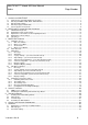
NAUTICAST™ Inland AIS User Manual Index 1 STARTING THE NAUTICAST .................................................................................................................1 1.1 1.2 1.3 1.4 1.5 2 Initial Set Up of the NAUTICAST for operation ...............................................................................................1 Entering the MMSI / IMO / DAC / ESN Numbers ............................................................................................2 Entering Ship Settings ..
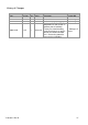
History of Changes Date 2005-11-01 2006-07-25 2006-11-06 Version 1.0.0 1.0.1 1.0.2 Rev. A B C Status Released Released Released 2008-12-05 1.0.5 D Released Y1-03-0211 Rev D Comments Initial Release Editorial work Screen Display Updates Update according to VTT&T, Adaptation for new function in Software 2.0.S116.W225, Factory Password handling, removed reference to specific default password and noted this is now on the protective cover on the unit display. Responsible A. Lesch M.D‟Arcangelo M.
1 Starting the NAUTICAST 1.1 Initial Set Up of the NAUTICAST for operation NOTE: AUTHORITIES MANDATE THAT YOU ENTER THIS INFORMATION. After installing the antennas and hardware the following User, Voyage related and Ship Settings data needs to be entered. Upon Start-up (Applying power) enter the following information. a) Enter MMSI Number - See paragraph 1.2 on entering information. During the initial boot or after “factory settings” the user is asked to enter a valid MMSI number.
1.2 Entering the MMSI / IMO / DAC / ESN Numbers Select from the Main Menu “Service Configuration” Number 6. The default password from the factory is mentioned on your AIS display at the protection foil. (see Appendix 7.3 for password information). Enter Service Password and use the up and down arrows on keypad to select “Change MMSI / IMO” than press M5 “Select” or “by pressing number 3 on the keypad. Input your MMSI and IMO number and press Save to store data. Unit will reboot itself after pressing Save.
N 1o21' E 0o14' |1> N/A|2>0.00|3>0.10nm ********** Change MMSI / IMO *********** MMSI :119302468 IMO No.:303174162 ---------------------------------------NUM| Save | | | Back Select Submenu 4 “Change DAC / ESN” with cursor button [Up] & [Down] by pressing No. 4 on the keyboard. N 1o21' E 0o14' |1>0.01|2>1.30|3>1.80nm |---------------------------------| 6. Service Configuration -----| | | +- 1. Change Service Password View | +- 2. User Password Settings | +- 3. Change MMSI / IMO -----| +- 4.
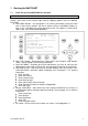
1.3 Entering Ship Settings Select from the Main Menu “Ship Settings” Menu is USER password protected. The default password from the factory is mentioned on your AIS display at the protection foil. (see Appendix 7.3 for password information). Enter Password and use the up and down arrows to edit Ship Settings then press Enter or the numeric reference on the keypad to select and edit. Save after editing. Main Menu Example: N 1 o23' E 0 o16' |1>0.01|2>1.30|3>1.
Setting the Internal and External GPS Antenna Position. NOTE: It is critical for the proper orientation of your ship to other AIS users to enter this data accurately. Example: Length of ship / convoy = 220m and Beam of ship / convoy = 43m. GPS ANTENNA location on ship (is x in above Menu example) is located 200 meters from bow (A) and 33 Meters from Starboard side (D). NOTE: You can only enter Dimension A and D. B and C are automatically calculated.
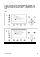
Sub Menu N 1 o18' E 0 o12' |1>0.01|2>1.30|3>1.80nm |---------------------------------| 3. Voyage Settings -----| | | +- 1. General Settings View | +- 2. Cargo / Voyage | +- 3. Persons on Board -----| +- 4. Destination | Msg. | | -----| | Displ| | ---------------------------------------NUM|Select->| | |<-Back Select Submenu 1 “General Settings” with cursor button [Up] & [Down] by pressing No. 1 on the keyboard. N 1o18' E 0o12' |1>0.01|2>1.30|3>1.80nm ***********General Settings************* Draught[x.
Select Submenu 2 “Cargo/Voyage Settings” with cursor button [Up] & [Down] or by pressing No. 2 on the keyboard. N48°12' E 16°26' |1> N/A|2> N/A|3> N/Anm ******** Cargo/Voyage Settings ********* ERI ship type Blue Cones Un/ Loaded : : Default/Unknown : Default/Unknown ---------------------------------------| Save | | | Exit Toggle the values for the ERI ship type (see Appendix 7.
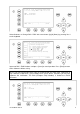
Mask input: Scroll the Data Fields with [Enter] and input the UN destination codes as well as the ETA (estimated time of arrival) data. Save the new settings by pressing [Save], and return to the Main Menu Screen by pressing [Exit]. Press [Exit] to return to the Main Menu without saving any changes. N 1o18' E 0o12' |1>0.01|2>1.30|3>1.
1.5 Service and User Passwords WARNING: It is very important that the Service password not be lost. The default password from the factory is mentioned on your AIS display at the protection foil. (see Appendix 7.3 for password information). Keeping the password in a second location may be wise. Memorizing the password is best. If you lose this password, you cannot make any further configuration changes: Access to the AIS is blocked.
Service Menu Example: N 1o21' E 0o14' |1>0.01|2>1.30|3>1.80nm |---------------------------------| 6. Service Configuration -----| | | +- 1. Change Service Password View | +- 2. User Password Settings | +- 3. Change MMSI / IMO -----| +- 4. Restore Factory Settings | Msg. | | -----| | Displ| ---------------------------------------NUM| Select->| | |<-Back Service Password Menu Example: N 1o25' E 0o18' |1>0.10|2>1.30|3>1.
Changing the User Password Select Submenu 2 “User Password Settings” with cursor button [Up] & [Down] by pressing number 2 on the keyboard. N 1o21' E 0o14' |1>0.01|2>1.30|3>1.80nm |---------------------------------| 6. Service Configuration -----| | | +- 1. Change Service Password View | +- 2. User Password Settings | +- 3. Change MMSI / IMO -----| +- 4. Restore Factory Settings | Msg.
Press Save to store the changes. 2 NAUTICAST™ Inland AIS User Interface Soft Keys [M1] – [M8] Safety Keys Display Navigation Screen Header (1 or 4 lines) Ship Details 12 lines Or Menu Structure 14 lines Keyboard 2.1 Enter Key Cursor Cross NAUTICAST Keyboard The NAUTICAST is fitted with a full alphanumeric keyboard, with the following functions: By pressing any key on the keyboard the letters are addressed.
2.3 Explanation of the Num-Locked and [NUM] Functions The NUM-Locked function is enabled after pressing the Function [Fn] Key and the Shift [] Key. It is possible to disable the Num-Lock Function by pressing the Shift [] Key. NOTE: The NAUTICAST automatically changes the keys “Q” through to “P” to numerical input when the current application requires numbers, rather than letters to be input. This feature is enabled when [NUM] appears on the bottom left hand side of the screen. 2.
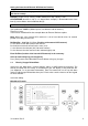
3 NAUTICAST Screens The advanced version of the NAUTICAST offers three display modes: Navigation Screen - Standard screen, automatically visible Menu Structure - Visible after pressing the [Menu] Soft Key Graphical User Interface - The Graphical User Interface is visible after pressing the [M2] Soft Key (new mode) 3.1 Navigation Screen This screen provides the user with Navigation Data from their own vessel and lists all other vessels within receiving range.
3.1.1 Own Vessel Data LAT:N LON:E 1°27.845'ExtSOG:34.6kn 0°21.289'ExtCOG:173.0° 05/26/06 10:52:26 LAT: Latitude LON: Longitude Date: The actual UTC - date (MM.DD.YY) and time (hh.mm.ss) are displayed on the top right hand corner of this view. IntGPS: 3D A/ IntGPS ExtHDT:222° Reg6 Indicates normal or differential mode of GPS position. 2D or 3D: Indicates the precision of the GPS result. Indicates the used position source: intGPS.
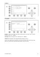
3.1.2 Other Vessel Data 001/021..SHIPNAME....RNG.BRG..SOG..COG.. (E.g: Vessel 01 of 021) current or selected Vessel/ Total number of Vessels 001/021 (max. 256 Vessels) ShipName: Name of the Ship and AIS – Type: Cl-A: SOLAS Class-A Ship Cl-B: Leisure Craft Base: Base station SAR : Search and Rescue Aircraft RNG Vessel Range Note: The vessel closest to own ship, or where position data is unknown (N/A), is listed first.
3.1.4 Other Vessel Details This screen shows the Dynamic, Voyage and Vessel Related Data, which is currently being transmitted by a previously selected vessel. N48°12' E 16°26' |1> N/A|2> N/A|3>1.80nm Time 2:07 -----------------POS:001/021 LAT : S 74o o50.231' LONo :W 9o 34.192' Heading :77 ROT :-0.2 /min l IMO No. :90733283 MMSI: 211180260 ShipName: DONAUPLUS AT:DD3684 ShipType:Cargo ship Length :310m Beam:73m RefPoint:A190 B120 C10 D>=63m Cargo :N/A or harmless Draught :3.3m Dest.
This information indicates the Reference Point of the used GPS Antenna onboard the vessel. RefPoint:A190 B120 C10 D<63m A: 190m B: 120m C: D: 10m >63m (means more than 63m in the case of a very large vessel) Vessels Cargo: Indicates the type of cargo on board. N/A or harmless Further Vessel Details: Draught : 3.
To call up the Main Menu, press the [Menu] button once, and all Submenus are displayed. The cursor position indicates the selected submenu. Menu navigation is achieved by pressing the [Up] or [Down] keys to select, and then by pressing [Enter] to confirm the desired Submenu selection. To escape from any Submenu and returning to the Navigation Screen, press the [M2] button at any time. The own vessel‟s current Navigation Information is continuously displayed on the first line.
NOTE: The navigation screen automatically appears after some seconds of user inactivity on the transponder, or immediately by pressing the [Menu] button in the Main Menu. 3.4 Sub-Menus OverviewMessages N 1o19' E 0o12' |1>0.10|2>1.30|3>1.80nm |---------------------------------| 1. Messages -----| | | +- 1. Write Addressed SRM View | +- 2. Write Broadcast SRM | +- 3. Lock Request -----| +- 4. Inbox History | +- 5. Inbox SRM Msg. | +- 6. Inbox LRI | +- 7. Inbox Lock Reply -----| +- 8.
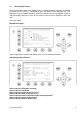
3.4.4 Ship Settings – (User Password Protected) N 1o19' E 0o12' |1>0.01|2>1.30|3>1.80nm ************ Ship Settings ************* Atis Code :max. 7ASCII +------+ ShipName :NAUTICAST(TM) INLAND AIS | | Length(Conv):400m | A Beam(Conv) :32m | | RefPtExt :A380 B20 C8 D24m | x--| RefPtInt :A380 B20 C8 D24m | | B Length(ship):600dm | | | Beam(ship) :220dm +-C-+D-+ ---------------------------------------| Save | | | Back 3.4.5 Transponder Configuration – (User Password Protected) N 1o19' E 0o12' |1> N/A|2>0.
3.4.7 Display Settings N 1o21' E 0o15' |1>0.10|2>1.30|3>1.80nm *********** Display Settings *********** Mode | +-[*] Day Min Max | +---- Brightness:<9> [*********] | +---- Contrast : 6 [****** ] | | +-[ ] Night Min Max +---- Brightness: 3 [*** ] +---- Contrast : 2 [** ] ---------------------------------------NUM|DayNight| | | Back 3.4.8 Graphical Display Settings N 1o46' E 0o39' |1>0.10|2>1.30|3>1.80nm |---------------------------------| 8 Graphical Display Settings -----| | | +- 1.
3.5 Sub-Menus Detailed 3.5.1 Messages N 1o19' E 0o12' |1>0.10|2>1.30|3>1.80nm |---------------------------------| 1. Messages -----| | | +- 1. Write Addressed SRM View | +- 2. Write Broadcast SRM | +- 3. Lock Request -----| +- 4. Inbox History | +- 5. Inbox SRM Msg. | +- 6. Inbox LRI | +- 7. Inbox Lock Reply -----| +- 8.
a) Writing an Addressed Message To write a Safety Related Message first select an addressee from the Vessel Listing. This is possible by using the cursor buttons [Up] and [Down], and confirming the selection with [Enter] or [Select]. LAT:N 48°12.177'IntSOG:0.0kn 02/25/2008 LON:E 16°26.166'IntCOG:0.0° 15:08:29 IntDGPS:3D /B Reg1 ! 3A 2T BluSign: OFF AISMode: INLAND 012/034..ShipName....RNG.BRG..SOG..COG.. WACHAU [Cl-A] 1.50 320 0.0 208.2 OSB WIEN_____[Cl-A] 1.57 319 0.1 298.4 TWIN CITY LIN[Cl-A] 1.73 319 0.
Dynamic Keys: Addressed Message Editor [M5] [Send] Send Message [M6] [Channel] Select Transmission Channel [M7] [Channel] Select Transmission Channel [M8] [Back] Return Listing to [Enter] Send Message Vessel c) Confirmation of Sent Addressed Message The confirmation screen shows the successful message transmission and indicates which channels (AIS1 or AIS2) were used. Successful Message Transmission on Channel AIS1: LAT:N 1oo18.963'ExtSOG:34.6kn 11/21/2002 LON:E 0 12.408'IntCOG:173.
It is possible, that the recipient‟s Transponder could not receive the message at all, and in this case the following screen is displayed. It is then recommended to resend the message. Unsuccessful Message Confirmation (no acknowledgement) N 1o19' E 0o12' |1>0.10|2>1.30|3>1.
e) Confirmation of Broadcast Sent Message This Confirmation Screen shows that the message was successfully transmitted on the Broadcast Setting. By pressing [Back] the user automatically returns to the Message Editor for further Messaging. The [SendTo] returns the user to the Vessel Listing, with the option of further Message Writing to individual vessels. N 1o19' E 0o13' |1>0.10|2>1.30|3>1.
LAT:N 1oo20.256'ExtSOG:34.6kn * 1L o LON:E 0 13.700'ExtCOG:173.0 07:44:49 o IntGPS: 3D ExtHDT:222 Reg6 SRM /B 001/021..ShipName....RNG.BRG..SOG..COG.. LAT:N 48°12.177'IntSOG:0.0kn 02/25/2008 LON:E 16°26.166'IntCOG:0.0° 15:08:29 IntDGPS:3D /B Reg1 ! 3A 2T BluSign: OFF AISMode: INLAND 012/034..ShipName....RNG.BRG..SOG..COG.. WACHAU [Cl-A] 1.50 320 0.0 208.2 OSB WIEN_____[Cl-A] 1.57 319 0.1 298.4 TWIN CITY LIN[Cl-A] 1.73 319 0.1 220.4 ADMIRAL TEGET[Cl-A] 1.80 319 0.1 214.2 VINDOBONA____[Cl-A] 1.83 319 0.0 224.
N 1o20' E 0o13' 1>0.10|2>0.00|3>0.10nm ************** Inbox LRI *************** LRI 07:44 5004 TEXT TO LRI SENDER CAN BE INPUT HERE 07:44 11/28 ------------------ POS:01/01 LRI 5004 ACK ---------------------------------------| | | Reply | Back An LRI has arrived; the NAUTICAST Settings are configured to Manual Mode: The LRI therefore needs to be manually handled (accepted or rejected) N 1o20' E 0o14' ||1>0.10|2>1.
N 1o19' E 0o13'|1>0.10|2>1.
ASRM 13:43 PIRATE ATTACK! 5264 Addressed Safety Related Message, acknowledged by recipient, arrived at 13:43, with text “Pirate Attack”, from vessel with MMSI 5264 ASRM*13:42 HIGH WINDS IN AREA! 5004 Addressed Safety Related Message, unacknowledged by recipient, arrived at 13:42, with text “High winds in area!” from vessel with MMSI number 5004 ALR 13:40 external EPFS lost 25 Alarm, no longer active (revoked) with ID Number 25 (see Alarm Types), revoked at 13:40 with text “external EPFS lost” ALR!*13:38 gen
ASRM: Information Time 17:39 Date 11/26 (mm.dd) POS 01/02 (Message 01 of 02) Message Type AddressedSRM Status * (not acknowledged) MMSI of Sender 5004 Channel Incoming AIS Channel ACK Message not yet acknowledged ALR – Reading Incoming Alarms: N 1o27' E 0o21' |1>0.10|2>1.30|3>1.
h) Writing a “Estimated Time of Arrival” (ETA) Message Upon selection of “3. Lock Request” in the Message Menu, the Lock Request (ETA) Editor appears. The Message contains: - The address of the recipient of this ETA – Message (the default is “2000000”). The address could be received from the authority. - The RIS Identifier / location code of the Lock. This code is divided into 5 parts. It has to be keyed in with the UN - values of that particular destination. - The number of tug boats that are required.
i) Inbox of a received “Requested Time of Arrival” (RTA) Message Upon selection of “7. Lock Reply” in the Message Menu, the received Reply to your ETA – Message appears. The Message contains: - The timestamp of this message in the format MM/DD hh:mm. - The location code of the Lock - The requested time of arrival at the lock in the format MMDDhhmm (month-day-hourminute). - The status of the lock (operational / not operational). N 1o22' E 0o16' |1> N/A|2>0.00|3>0.
Mod.: AIS Transmission Mode AU Autonomous AS Assigned IN Interrogation/Polled Mode ?? Unknown Used Channel AIS1, AIS2 Syn.: (UTC source) D UTC direct I UTC indirect B Sync to Base A Sync to mobile with the most received stations (Semaphore) RXVe: Total number of all received stations by the individual vessel. MMSI: MMSI number of the individual vessel.
Reference Point (in meters): This information indicates the Reference Point of the used GPS Antenna onboard the vessel. RefPoint: A190 B120 C10 D>63m A: B: C: D: 190m 120m 10m >16m Vessels Cargo: Indicates the type of cargo on board N/A or harmless Further Vessel Details: Draught : 3.
N 1o22' E 0o16' |1>0.10|2>1.30|3>1.80nm ************* Version Info ************* ## # # #### # # # # # ### # # # ## # # # ### ### # # # # ### # # ### # # # # ## # # #### # # # # # # ### ## # # ##### ## # ## # # # ### # Hardware: AIS Transponder Class A Software: INLAND V2.0.S116.nnnn SW Stamp: Month Day Year Date Modem HW: Issue J SeCo:n Modem SW: 01.10.
N 1o20' E 0o13' |1> N/A|2>0.00|3>0.10nm |---------------------------------| Menu -----| | | +- 1. Messages View | +- 2. AIS Status | +- 3. Voyage Settings -----| +- 4. Ship Settings | +- 5. Transponder Configuration Msg. | +- 6. Service Configuration | +- 7. Display Settings -----| +- 8.
The password query field appears. Input new User Password and press [Enter]. N 1o31' E 0o24' |1>0.01|2>1.30|3>1.80nm ---------------------------------------++++++++++++++++++++++++++++++++++++++++ User password protected! Please enter user password: ++++++++++++++++++++++++++++++++++++++++ ---------------------------------------| Enter | | | Exit ++++++++++++++++++++++++++++++++++++++++ N 1o18' E 0o12' |1>0.01|2>1.30|3>1.80nm |---------------------------------| 3. Voyage Settings -----| | | +- 1.
N 1o18' E 0o12' |1>0.01|2>1.30|3>1.80nm ***********General Settings************* Draught[x.xx m ]: 20.00m Airdrauht[cm]: 3500cm NavStat.
Select Submenu 3 “Persons on Board” with cursor button [Up] & [Down] or by pressing No. 2 on the keyboard. N 1o18' E 0o12' |1>0.01|2>1.30|3>1.80nm ************* PoB Settings ************* Crew Members:0-254 (255 = unknown = default) Passenger :0-8190(8191= unknown = default) S.
Input String: Direct input of the destination string. ETA(estimated time of arrival) has to be entered separately N 1o18' E 0o12' |1>0.01|2>1.30|3>1.
Mask input: Scroll the Data Fields with [Enter] and input the UN destination codes as well as the ETA (estimated time of arrival) data. Save the new settings by pressing [Save], and return to the Main Menu Screen by pressing [Exit]. Press [Exit] to return to the Main Menu without saving any changes. N 1o18' E 0o12' |1>0.01|2>1.30|3>1.
3.5.3 Ship Settings (User Password Protected) Select “Ship Settings” with cursor button [Up] & [Down] or press No. 4 on the keyboard. NOTE: Please see Appendix 7.3 for password information N 1o23' E 0o16' |1>0.01|2>1.30|3>1.80nm |---------------------------------| Menu -----| | | +- 1. Messages View | +- 2. AIS Status | +- 3. Voyage Settings -----| +- 4. Ship Settings | +- 5. Transponder Configuration Msg. | +- 6. Service Configuration | +- 7. Display Settings -----| +- 8.
Example: Length (of the complete convoy) = 400m Beam (of the complete convoy) = 32m Internal GPS-Antenna is mounted 20 metres from stern and 24 metres from starboard. Length(Conv) Beam(Conv) RefPtExt RefPtInt : 400 : 32 : : B20D24 (no spaces, no decimals, no commas) The full line as shown will be displayed after pressing Enter: RefPtInt : A380 B20 C8 D24m (A and C are calculated by the AIS). Enter RefPtExt (location of the external GPS antenna) in the same way.
After the Ship Settings have been input and saved, this screen appears. [Exit] takes the user back to the Main Menu. N 1o30' E 0o24' |1>0.10|2>1.30|3>1.80nm ---------------------------------------- ++++++++++++++++++++++++++++++++++++++++ Data saved.
3.5.4 Transponder Configuration (User Password Protected) The Configuration Menu allows the user to alter the hardware-based parameters. User Password Configuration is also undertaken here. Accessing the Configuration Settings: The Configuration Menu is User Password protected. NOTE: Please see Appendix 7.3 for password information. N 1o22' E 0o15' |1> N/A|2>0.00|3>0.10nm |---------------------------------| 5. Transponder Configuration -----| | | +- 1. Change User Password View | +- 2.
Incorrect User Password Input If the incorrect User Password is input, the screen below appears. N 1 o34' E 0 o27' |1>0.10|2>1.
N 1 o33' E 0 o27' |1>0.10|2>1.30| * 1A1L ********* Change User Password ********* Enter new password: Repeat new password: ***** ***** {Length: 4..8 characters} ---------------------------------------| Enter | | | Back Dynamic Keys: Initial User Password Setting [M5] [Enter] Confirm User [M8] Password Input [Back] Return to Menu Configuration This screen appears if the new User Passwords are mismatched - i.e. the New User Password and the Repeated New User Password are not identical.
The new User Password configuration has been saved. N 1 o33' E 0 o27' |1>0.10|2>1.30| * 1A1L ---------------------------------------- ++++++++++++++++++++++++++++++++++++++++ Data saved. ++++++++++++++++++++++++++++++++++++++++ ---------------------------------------| | | | <-Exit b) Region Settings A Region is a defined area, with specific VHF parameters, which are sent out by Vessel Traffic Service Stations (VTS), and received via Digital Selective Calling (DSC) or AIS.
Overview of Region Settings Name Region Number Number of pre-defined Region Valid OK Status of Region Setting - OK: Stored and Valid Source A:AddrChM A: Addressed Channel Management (Msge. 22) Source: VTS via AIS B:BcastChM B: Broadcast Channel Management (Msge.
Input Modes for New Regions Data Field Field Description Input Modus Additional Information NE LAT(1) Latitude N/E corner Manual Input Degrees and minutes NE LON(1) Longitude of N/E corner Manual Input Degrees and minutes SW LAT(2) Latitude of S/W corner Manual Input Degrees and minutes SW LON(2) Longitude of S/W corner Manual Input Degrees and minutes TrZone(3) Transitional Zone Size Nautical Miles ChannAIS1 Primary AIS Channel Manual Input Channel Number BandwAIS1
d) Interrogation Settings This screen allows settings for modes of response to Long Range Interrogation Requests (LRI). It is possible to set the AIS station to respond automatically or manually to LR Interrogations, and determine which vessel data may be interrogated. It is further possible to reply to incoming LRI‟s. Long Range Interrogation Settings: N 1 o19' E 0 o13' |1>0.10|2>1.30|3>1.
Replying to a Long Range Interrogation Request: The arrival of an LRI is shown in the Navigation Screen (top right hand corner: * 1L) The detailed LRI is automatically stored in Menu 1:Messages, Submenu: 6 Inbox LRI, where the request can be read and replied to. LAT:N 1 oo20.261'ExtSOG:34.6kno * 1L LON:E 0 13.705'ExtCOG:173.0 13:37:34 o IntGPS: 3D ExtHDT:222 Reg6 /B 001/021..ShipName....RNG.BRG..SOG..COG.. 1>DOREEN-----------> N/A 120 22.2 301.5 2>FINE EAGLE------->0.00 N/A 13.1 359.
e) Sensor Settings Within this service password protected menu the NAUTICAST offers the following configuration options: Set up data speed 4800/9600/38400 baud. Monitor the connected sensor inputs for each sensor channel. Verify and edit the Sensor Configuration on the display screen. Analyze the information received from the connected sensor devices. Produce an electronic installation report. Configuration of various NMEA protocols. N 1o19' E 0o12' |1> N/A|2>0.00|3>0.
f) Inland AIS Configuration / Blue Sign This screen allows the user to toggle the quality of the speed, course or heading information received from an external device. These settings are normally set to low. NOTE: It is highly recommended to keep the settings on low. Blue Sign: Toggle the value from to when a Blue Sign switch is connected. Setting the blue sign can be done by an external hardware switch.
3.5.5 Service Configuration (Service Password Protected) The Service Configuration Menu allows initial configuration of the Service Password, Password Settings (on/off), MMSI/IMO Numbers and the option of resetting the NAUTICAST to Factory Settings. The Service Password is required in order to enter the Service Configuration Menu.
g) Change Service Password This screen provides a means to individually configure the Service Password. This password differs from the User Password as it allows the user access to the Menu „Service Configuration“. A minimum of 6, a maximum of 8 characters are allowed. The process of configuring the Service Password is identical to that of User Password configuration (see Menu 5: Configuration, Submenu 1: Change User Password). N 1o25' E 0o18' |1>0.10|2>1.30|3>1.
h) User Password Settings N 1o24' E 0o18' |1>0.10|2>1.30|3>1.80nm |---------------------------------| 6-2. User Password Settings -----| | | +- 1. Change User Password View | +- 2. Change Password Protection | -----| | Msg. | | -----| | Displ| ---------------------------------------NUM| Select->| | |<-Back Change User Password Protection: This function allows the user to enable or disable the User Password Query Function.
i) Changing the MMSI / IMO / DAC / ESN Numbers Mentioned DAC and ESN numbers are only available in Inland AIS - Mode . Select again “Service Configuration” from the Main Menu with the cursor button [Up] & [Down] or press No. 6 on the keyboard. Select Submenu 3 “Change MMSI/IMO” with cursor button [Up] & [Down] by pressing No. 3 on the keyboard. N 1o21' E 0o14' |1>0.01|2>1.30|3>1.80nm |---------------------------------| 6. Service Configuration -----| | | +- 1. Change Service Password View | +- 2.
Select Submenu 4 “Change DAC / ESN” with cursor button [Up] & [Down] by pressing No. 4 on the keyboard. N 1o21' E 0o14' |1>0.01|2>1.30|3>1.80nm |---------------------------------| 6. Service Configuration -----| | | +- 1. Change Service Password View | +- 2. User Password Settings | +- 3. Change MMSI / IMO -----| +- 4. Change DAC / ESN | +- 5. Change AIS Mode Msg. | +- 6.
j) Changing the AIS Mode Select “Service Configuration” from the Main Menu with the cursor button [Up] & [Down] or press No. 6 on the keyboard. N 1o19' E 0o13' |1>0.01|2>1.30|3>1.80nm |---------------------------------| Menu -----| | | +- 1. Messages View | +- 2. AIS Status | +- 3. Voyage Settings -----| +- 4. Ship Settings | +- 5. Transponder Configuration Msg. | +- 6. Service Configuration | +- 7. Display Settings -----| +- 8.
Select Submenu 5 “Change AIS Mode” with cursor button [Up] & [Down] by pressing No. 5 on the keyboard. N 1o21' E 0o14' |1>0.01|2>1.30|3>1.80nm |---------------------------------| 6. Service Configuration -----| | | +- 1. Change Service Password View | +- 2. User Password Settings | +- 3. Change MMSI / IMO -----| +- 4. Change DAC / ESN | +- 5. Change AIS Mode Msg. | +- 6.
k) Restore Factory Settings CAUTION: By acknowledging the return to Factory Settings Command, all previous settings, both the User and Service Passwords and all manually input data are automatically deleted! N 1o20' E 0o13' |1>0.10|2>1.30|3>1.80nm ******* Restore Factory Settings ******* Really overwrite all settings? Note: This also affects both passwords.
3.5.6 Display Settings It is possible to choose from Daylight and Nightlight Display Settings; it is further possible to adjust the Brightness and Contrast Settings for both Display Settings. The maximum setting for Brightness and Contrast is <9>, the minimum setting is <0>. It is possible to automatically switch the Display Settings on the NAUTICAST to Day or Night Settings from any Menu Screen by pressing the [M4] [Displ] button. N 1o20' E 0o14' |1>0.10|2>1.30|3>1.
The main features of this Graphical User Interface (GUI) are the two new view options: - Radar View The typical way of presenting traffic information on screens - Fairway View This type of view is oriented to the current course over ground (COG) and supports the operator with information related to this particular region Remarks - In both views it is possible to zoom in and out to get more detail or a better overview of the visual content.
3.6.1 Switching between the Views Navigation Screen LAT:N 1oo27.845'ExtSOG:34.6kn 05/26/2006 o LON:E 0 21.289'IntCOG:173.0 10:52:26 o IntGPS: 3D ExtHDT:222 Reg6 A/ 001/021..ShipName....RNG.BRG..SOG..COG.. 1>DOREEN-----------> N/A 120 22.2 301.5 2>FINE EAGLE------->0.00 N/A 13.1 359.9 3>SYLVAEPSILON----->0.10 23 32.1 203.2 4>ESSOTOKYO-------->0.43 99 10.0 120.3 5>OLYMPIAHIGHWAY FE>0.59 342 21.2 50.0 6>SANEI------------>0.80 272 32.1 270.1 7>KATOO------------>1.00 321 21.2 200.8 8>OLYMPIA PALACE--->1.
3.6.2 The Radar View This screen provides the user with a commonly used way of representing ship objects on an electronic device. The Radar View is northern orientated, as indicated by the compass on the very right top of the screen. Other AIS targets Own ship position Distance rings around the own position The Elements of the Radar View: Own Ship: A symbol for the own ship is displayed in the middle of the screen.
Dynamic Keys: Radar View [M1] Set filter option on AIS Targets [M2] Switch between the views [M3] Show alarm window [M5] Acknowledge alarms or safety related messages (SRM) [M7] Acknowledge SRM and reply [Menu] Selects the Main Menu [Up] / [Down] / Activate the minimized radar view [Left] / [Right] [FN] + Change the zoom level [Up] / [Down] [Shift]+ Scroll the view (only available in radar view) [Up] / [Down] / Zoom Levels To adjust the Radar View following zoom levels are implemented (default is zoom level
This screen shows a 1 step scrolling in a southern direction. This screen shows a 2 step scrolling in a southern direction. The Minimized Radar View The minimized radar view shows a split screen. On the left hand side a Ship List is displayed, on the right hand side a minimized view of the Radar View is visible. This view will be displayed, if one of the cursor keys is pressed.
minimized Radar View Ship List [M4] “Message Write” Button [M6] Ship List / Minimized View Switch [M8] Exit Button The Elements in the Minimized Radar View: “Message Write” Button: By pressing the [M4] button, a message can be sent to an AIS target that is currently selected in the Ship List. Ship List: This list shows the same targets as shown in the Navigation Screen. Ship List / Minimized View Switch: This switch indicates whether targets can be selected from the Ship List or from the minimized view.
Ship Details If a target is selected by pressing [Enter], whether in the Ship List or directly in the graphical view, the corresponding ship details are displayed instead of the minimized view. Pressing [Up] or [Down] scrolls the ship detail list by line, [Left] or [Right] by page. [M8] returns to the minimized view. 3.6.3 The Fairway View The Fairway View shows the course over ground (COG) orientated view of the Information screen data.
Compass Fairway Lines AIS Targets Own Ship Horizontal Lines Y1-03-0211 Rev D 73
The Elements in the Fairway View: Compass: Shows the current COG. Fairway Lines: The Fairway Lines are border lines of a virtual fairway oriented on the actual course over ground. AIS-Targets: Other AIS targets received via VHF are displayed, if their distance is within the range of the current zoom level. Own Ship: A symbol for the own ship is displayed in the middle of the screen and can not be changed. Horizontal Lines: The horizontal lines are the equivalent to the radar views distance rings.
Zoom Level 2 would look like this: The Minimized Fairway View The minimized Fairway View shows a split screen. On the left hand side a Ship List is displayed and on the right hand side a minimized Fairway View is seen. This view is displayed, if one of the cursor keys is pressed.
Ship List / Minimized View Switch: This switch indicates whether targets can be selected from the Ship List or from the minimized view. If the arrow above the [M6] points to the left, targets can be selected from the Ship List with the [Up] and [Down] buttons. If the arrow above points to the right, targets can be selected from the minimized view with the [Up] or [Down] or [Left] or [Right] buttons. Regardless on which side of the screen targets are selected, both views correspond to each other.
3.6.4 Message and Alarm Handling Alarms If an alarm occurs, the symbol to the right of the [M3] button becomes visible. M3 Alarm Icon Pressing the [M3] button shows the details of the selected alert. Pressing [M5] leads to alarm acknowledgement and the closure of the window as well as the alarm icon disappearing. An alarm could occur at every time so the alarm icon can be seen in every view (in the big views as well as minimized views and ship details list).
3.6.5 Configuration of the Graphical Display General The configuration of the Graphical Display could be accessed over the entry point 8 of the Main Menu. N 1o46' E 0o39' |1>0.10|2>1.30|3>1.80nm |---------------------------------| Menu -----| | | +- 1. Messages View | +- 2. AIS Status | +- 3. Voyage Settings -----| +- 4. Ship Settings | +- 5. Transponder Configuration Msg. | +- 6. Service Configuration | +- 7.
Sub-Menu Fairway View Scale Content Settings of the Geometry and Scale of the Fairway View Symbol settings of the Fairway View (also the minimized Fairway View) Symbol settings of the Radar View (also the minimized Radar View) AIS-target filter settings; enabling / disabling the Auto Zoom feature; Alarm appearance Fairway View Symbols Radar View Symbols Other Graphical Settings Fairway View Scale N53°31 E10° 1 |1>0.69|2>0.77|3>1.
NOTE: The Fairway View is a “non linear View”. The following drawing illustrates the parameters from the Fairway View Scale Menu and additionally presents the transformation process from the Radar View to the Fairway View. 260° 325.
Fairway View Symbols N53°31 E10° 1 |1>0.69|2>0.77|3>1.08nm *********** Fairwayview Symbols ********* Fairwayview Symbols Own Ship : Other Targets: 3D Minimized Fairwayview Symbols Own Ship : Solid Other Targets: Reduced(3x3) ---------------------------------------NUM| Save | | | Back Dynamic Keys: Fairway View Symbols [M5] [Save] Save the settings [M8] Return to [Back] Graphical Display Menu The symbols for the own ship and for other targets could be selected individually.
Radar View Symbols N53°31 E10° 1 |1>0.69|2>0.77|3>1.
Other Settings Inside this menu it is possible to adjust the graphical view to your demand. The available functions cover the topics: o AIS-target filter settings o Enabling / disabling the Auto Zoom feature with max. number of ships o Alarm appearance N53°31 E10° 1 |1>0.69|2>0.77|3>1.
Save On all of the described options inside the Configuration of the Graphical User Interface you could save your settings by pressing the [M2] Button. N 1o30' E 0o24' |1>0.10|2>1.30|3>1.80nm ---------------------------------------- ++++++++++++++++++++++++++++++++++++++++ Data saved.
4.1 MOB Person over Board By pressing the MOB button the current navigation position of own vessel and time of incident is automatically saved. The MOB message containing the distress information “Person Over Board” is automatically prepared for transmission as an Addressed or Broadcast Safety Related Message. By pressing the [Broadcast] button, the MOB Message is automatically sent to all vessels within receiving range.
4.2 Activating the SRM Safety Related Message Button The desired Distress Message Text can be selected by pressing the appropriate number on the keyboard. By pressing the [Exit] button, it is possible to escape from this screen without sending the SRM Message. NOTE: If no Message Subject is selected, the message is automatically sent as an undesignated distress call. N 1o22' E 0o15' |1>0.10 2>1.30|3>1.
Dynamic Keys: Send SRM Message [M5] Send selected [M8] SRM Message [Send] [Back] Return to SRM Message Selection Confirmation of sent SRM: Upon sending the SRM to all vessels the Broadcast Transmission Status is shown. The Broadcast Transmission Status Screen shows confirmation of sent message and allows the user to return to the Vessel Listing for further messaging to individual vessels. N 1o19' E 0o13' |1>0,10|2>1.30|3>1.
NOTE: The SRM message transmission is automatically repeated every 180 seconds until the [Stop] button has been pressed. Each SRM Message that is sent out every 180 seconds contains updated navigation information of own vessel position and actual time. N 1°18' E 0°12' |1> N/A|2>0.00|3>0.10nm -SRM----SRM----SRM----SRM----SRM----SRMMAYDAY,DE,ANDREA DORIA,D11233,1193046,PO S:N 1o19.006'_E 0o12.451'_UTC07:31 - F IRE, EXPLOSION Repeating SRM in 180 sec...
5 Troubleshooting 5.1 Reading and understanding Alarms: The NAUTICAST differentiates between Alarm and TXT messages. An Alarm informs the user about major system malfunctions and failings in the connected sensors. The Alarm Status informs the user about all active Alarms. The Alarm will be disabled and deleted from the Alarm Status, as soon as the displayed problem has been rectified. The TXT status displays additional sensor information and the UTC clock status.
5.2 Alarm Codes ID Description Text 01 02 03 04 05 AIS: Tx malfunction AIS: Antenna VSWR exceeds limit (VSWR Voltage Standing Wave Ratio) AIS: Rx channel 1 malfunction AIS; Rx channel 2 malfunction AIS: Rx channel 70 malfunction Cause/Source System Reaction / Remedy VHF Antenna, cabling Reaction: The transponder unit stops transmission. If Alarm ID 01 and ID 02 are simultaneously displayed, then a major antenna problem has arisen.
56 5.3 ID AIS: ENTER MMSI NUMBER No valid entered.
6 Contact and Support Information Contact your local dealer for NAUTICAST support. Please see our ACR Website for Service Listing. ACR Electronics Europe GmbH Handelskai 388 / Top 632 A-1020 Vienna, Austria Tel: +43 (1) 5 237 237 - 0 Fax: +43 (1) 5 237 237 - 150 Email: Technical.Support@acr-europe.com Web: www.acr-europe.com ACR Electronics Customer Service 5757 Ravenswood Road Fort Lauderdale, FL 33312, U.S.A. Tel.: +1 (954) 981-3333 Fax: +1 (954) 983-5087 Email: info@acrelectronics.com Web: www.
7 Appendix 7.
7.2 ERI ship types This table is used to automatically convert the selected UN ship types, which are used in Inland message 10, to the IMO types which are used in IMO message 5.
Msg 5 (1-99) Ship Type - SOLAS code U ship name dig1 dig2 Type (first digit) Cargo (Second digit) 8170 V Freightbarge with containers 8 9 Tanker No additional information 8180 V Tankbarge, gas 9 0 Other types of Ship All ships of this type 8210 C Pushtow, one cargo barge 7 9 Cargo Ships No additional information 8220 C Pushtow, two cargo barges 7 9 Cargo Ships No additional information 8230 C Pushtow, three cargo barges 7 9 Cargo Ships No additional information 8240 C Pus
Msg 5 (1-99) Ship Type - SOLAS code U ship name dig1 dig2 Type (first digit) Cargo (Second digit) 8441 V Ferry 6 9 Passenger Sips No additional information 8442 V Red cross ship 5 8 Medical transports - 8443 V Cruise ship 6 9 Passenger Sips No additional information 8444 V Passenger ship without accomodation 6 9 Passenger Sips No additional information 8450 V Service vessel, police patrol, port service 9 9 Other types of Ship No additional information 8460 V Vessel, work m
7.3 Password Settings This AIS transponder has two levels of password- protected security. The “User Password” gives access to user-level privileges and the ”Service Password” gives access to administrative privileges. The default password from the factory is mentioned on your AIS display at the protection foil. Once you have entered the system, please change the default password to your own passwords, for both levels of access. Use different passwords for the different security levels.
EG - Konformitätserklärung EC - Declaration of Conformity Diese Konformitätserklärung bestätigt, dass das unten benannte Produkt den Auflagen der EC Council Directive 96/98/EC vom 20 Dezember 1996 für maritime Ausrüstung, geändert durch die EC Council Directive 2002/75/EC vom 2. September 2002 entspricht und von der benannten Stelle Nr. 0735 (BSH) typengeprüft wurde. Darüber hinaus ist die Konformität gemäß Commission Regulation (EC) No.
EG - Konformitätserklärung EC - Declaration of Conformity Diese Konformitätserklärung bestätigt, dass das unten benannte Zubehör gleich oder besser dem im untenstehenden Zertifikat ausgewiesenen Zubehör ist. This declaration of conformity certifies that the mentioned accessory is equal or better to the equipment stated in the beyond Certificate.
EG - Konformitätserklärung EC - Declaration of Conformity Diese Konformitätserklärung bestätigt, dass das unten benannte Zubehör gleich oder besser dem im untenstehenden Zertifikat ausgewiesenen Zubehör ist. This declaration of conformity certifies that the mentioned accessory is equal or better to the equipment stated in the beyond Certificate.
EG - Konformitätserklärung EC - Declaration of Conformity Diese Konformitätserklärung bestätigt, dass das unten benannte Zubehör gleich oder besser dem im untenstehenden Zertifikat ausgewiesenen Zubehör ist. This declaration of conformity certifies that the mentioned accessory is equal or better to the equipment stated in the beyond Certificate.