Product Support Manual RCL-600A Remote Control Searchlight with Joystick Remote Control Panel Product No. 1941 & 1943 Y1-03-0139 Rev. C ACR Electronics, Inc. 5757 Ravenswood Road Fort Lauderdale, Fl 33312 Tel : +1(954) 981-3333 Fax: +1 (954) 983-5087 www.acrelectronics.com Email: Info@acrelectronics.
Foreword Congratulations and thank you for purchasing the ACR RCL-600A Remote Control Searchlight. The combination of superior design, high quality raw materials and quality controlled manufacturing produces a product that will perform for years to come. The test facility at ACR can reproduce some of the harshest environmental conditions known to man. This assures that the products we design and manufacture can stand up to the rigors found in a marine environment.
1.0 GENERAL The RCL-600A was specially designed for mariners who require a high intensity remote controlled searchlight that can stand up to the tough marine environment. The RCL-600A is a xenon arc searchlight that produces 6 million peak candle power. All functions of the RCL-600A can be electrically operated by remote control from the pilot area of the vessel. A remote control panel is supplied with the RCL-600A. An optional slave remote control panel is available (ACR Product No. 1942).
3.0 INSTALLATION AND OPERATION INSTRUCTIONS 3.1 Wiring of Unit The RCL-600A Remote Control Searchlight consists of Searchlight Unit and Master Remote Control Panel. The user must supply the cable and/or wire to power the unit. The source must be a fused 24 VDC, 10 Amp supply. This cable is to be attached to the Searchlight as shown in the connection diagram, Figure 1. Observe polarities when attaching wires! FIGURE 1 3 Y1-03-0139 Rev.
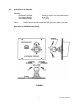
3.2 Remote Control Panel (Master) The Remote Control Panel can be mounted where desired using proper marine grade mounting hardware. For water-resistant installation, some sort of gasketing (neoprene sheet, silicone sealant, etc.) may be used. In all cases, the Remote Control Panel should be mounted in a protected area. Refer to Figure 2 for mounting and wiring details. FIGURE 2 4 Y1-03-0139 Rev.
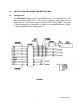
3.3 Wiring of Remote Control Panel (see Figure 3) The Remote Control Panel is received with a 6-foot long, 20 AWG cable. The cable will already be attached to the searchlight and should be connected to the remote control panel connector to row. Vinyl Castyre Cable 600V - VCT - 5.5sq - 2c + white Remote Control Panel 1 - black 1 red 1 2 2 3 3 4 4 5 5 6 6 7 7 8 8 9 9 10 10 11 11 12 Source DC 24V ± 10% 8.
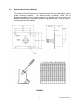
The preferred location for communication and navigation equipment systems antenna is at least 3 meters directly above the light. After the light is installed, all critical communication and navigation systems should be checked for proper operation with the light turned ON and rotated all around. FIGURE 4 6 Y1-03-0139 Rev.
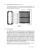
3.5 Second Remote Control Panel (Slave) – optional (Product No. 1942) The second Remote Control Panel may be mounted similar to the first. The second remote control panel is wired parallel to the first remote control panel. Connect cable to sockets on back of control panels. Master panel should have cable plugged into top socket row 2; slave panel should have cable plugged into bottom socket row 1 (refer to Figure 5). FIGURE 5 7 Y1-03-0139 Rev.
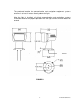
3.6 Instructions on Controls Rotation – Up/Down/Left/Right Low Speed Range High Speed Range Focus - Move joy stick in the desired direction. 0° to 7.5° 7.5° to 15° Rotate focusing knob for desired light spot size (wide or narrow) Operation of CPF99 Control Panel FIGURE 6 8 Y1-03-0139 Rev.
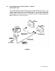
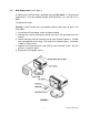
3.7 Bulb Replacement (see Figure 7) A 150W xenon short arc lamp is provided with your RCL-600A. If it should need replacement, it must be ordered through ACR Electronics, Inc., by P/N A1-140093. To replace the lamps: Warning: Do NOT touch glass or parabolic reflectors with fingers or tools! Use cloth gloves. 1. Disconnect unit from power source and allow cooling. 2. Remove four screws holding front flange and glass with provided 6mm hex wrench. 3.
Warning: Turn OFF the power witch when installing lamp. 1. Loosen the four (4) hexagon socket head cap bolts by using the attached hexagon wrench and take the front frame off from lamp housing. 2. Turn the anode female collet counterclockwise to loosen the anode male collet. 3. Take the xenon lamp out of the case. Hold the cathode side (-) before you and insert the anode side (+) into the anode male collet securely. 4. Turn the female collet clockwise to tighten the lamp. 5.
CONNECTION DIAGRAM, RCL-600A/12V Table 1 * Source cable size 0 – 30 ft run: 30 – 50 ft run: 50 – 100 ft run: ** AWG 12 AWG 8 AWG 6 Control cable size 0 – 100 ft run: *** AWG 16 Remote panels cable size 0 – 100 ft run: AWG 16 CONNECTION DIAGRAM, RCL-600A/24V Table 2 * Main cable and source cable size 0 – 30 ft run: 30 – 50 ft run: 50 – 100 ft run: ** AWG 14 AWG 12 AWG 10 Control cable size 0 – 100 ft run: *** AWG 16 Remote Panels Cable 0 – 100 ft run: AWG 16 11 Y1-03-0139 Rev.