PRODUCT SUPPORT MANUAL Y1-03-0158 Rev. D RCL-75 Product No. 1946 Remote Control Searchlight System ACR Electronics, Inc. 5757 Ravenswood Road Fort Lauderdale, Fl 33312 +1(954) 981-3333 · Fax +1 (954) 983-5087 www.acrelectronics.com Email: Info@acrelectronics.
TABLE OF CONTENTS 1.0 FORWARD .............................................................................................................1 2.0 SEARCHLIGHT......................................................................................................1 3.0 UNPACKING THE UNIT ......................................................................................2 4.0 WIRING ..................................................................................................................4 5.
1.0 FORWARD Congratulations and thank you for purchasing the ACR RCL-75 Searchlight. The combination of computer aided design; high quality raw materials and quality-controlled manufacturing produce a superior product. The Test Facility at ACR can reproduce some of the harshest environmental conditions known to man. This assures that the products we produce can stand up to the tough marine environment. With proper care and maintenance, your searchlight will be in service for years to come.
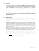
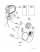
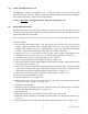
FIGURE 1 3.0 FIGURE 2 UNPACKING THE UNIT Every effort is made to assure that the RCL-75 has been delivered in good condition. It is important to make sure that all parts are present before you begin installation. (see Figure 3) The RCL-75 Searchlight contains the following: - Light Assembly Deck Mount 17’ wire harness Remote Control Point Pad™ and extra cover for flush mounting 4 ea. S/S Allen Bolts 4 ea. S/S Nuts 4 ea. S/S Flat washers 4 ea.
FIGURE 3 3 Y1-03-0158 Rev.
4.0 WIRING The RCL-75 has two wiring requirements: 1. Connect the remote control to the light 2. Connect the light to 12-volt power with 15 amp rated wiring. The light works best with 13.5 volts. Caution - The connectors on each side of the wire harness are different. Test fit connector to switch before running the harness to the light. A 17' wiring harness to connect the remote control to the light has been supplied for ease of installation. The wire should be run from the switch to the light.
Depending on the location selected, your light will need 1/4” diameter stainless steel bolts, nuts, and washers. If mounting area is robust enough panhead lag screws may be used. If the surface area can be reached from the under side, through bolting with lock nuts and washers should be used. 5.2 Tools and fasteners needed for installation 4 ea. 1/4” dia. bolts 4 ea. Lock nuts 4 ea. Washers 4 ea. 1/4” dia. Lag screws 1 ea. 1 ea. 1 ea. 1 ea. 1 ea.
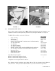
FIGURE 4 5.4.1 Surface Preparation for light Make sure surface is clean and dry. Verify that drill holes will not impact or harm other items (wires, plumbing, hardware or bulkheads). Decide on the use of screws or bolts. Can the backside of mounting surface be reached to install nuts and washers? Note: If the mounting surface is not flat, a special shapeable plate can be purchased, (P/N 9427), to adapt the light base to the surface. This plate can also be used to raise the light 1” if desired.
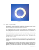
FIGURE 5 6.0 OPERATION The remote control Point Pad™ is simple to operate. A red LED tells you that power is available. A green LED lights when the light is in use. The ON/OFF button turns the dual beams ON and OFF. The control disk is pushed down in the direction you want to aim the light. Elevation and rotation can be operated at the same time and with the light in the ON or OFF mode. FIGURE 6 FIGURE 7 7 Y1-03-0158 Rev.
7.0 CARE AND MAINTENANCE The RCL-75 is relatively maintenance free. Clean the exterior of the light with a mild detergent and water if desired. Rotate the light left, then right and up then down periodically to keep motors and turning surfaces clean and operational. Caution – DO NOT rotate light manually. This will strip the gear rack. 8.0 BULB REPLACEMENT The bulbs are rated at over 200 hours of operation. If one burns out, you can replace it with a prefocused, desiccated bulb assembly from ACR.
17) Set reflector housing into the swivel sockets with the light pointed down and carefully engage the gear rack. (make sure the drain hole and serial number is facing down). 18) Form the loops in the bulb wires in the same shape as the ones removed. (looking into the back, the gear-toothed rack is on the right and the smooth arch is on the left).
FIGURE 10 FIGURE 11 FIGURE 12 FIGURE 13 FIGURE 14 FIGURE 15 10 Y1-03-0158 Rev.
FIGURE 16 FIGURE 17 FIGURE 18 FIGURE 19 11 Y1-03-0158 Rev.
9.0 RCL-75 SPECIFICATIONS (with Remote Control Point Pad™) 9.1 Specifications RCL-75 Power Requirements 12 – 14 Volts DC Current Draw 10 Amps Power Wire Leads 14 Gauge Wire harness Peak Beam Candle Power 17’ minimum with Molex quick connect locking connectors on each end 180,000 Candela* Lamp Dual beam 55 watt halogen Reflector Size 6” x 4.5” Beam Spread (degrees) Horizontal 8° Approx. Vertical 3° Approx. Elevation Angle (degrees) 9.
10.0 ACCESSORIES Here is a list of options and replacement parts that can be ordered for your searchlight. 1) 2) 3) 4) 5) 11.0 Product Number Mounting riser. 9427 This will raise the searchlight 1" from mounting surface to allow for clearance of deck hardware. It can be shaped to adapt light to uneven surfaces.