PRODUCT SUPPORT MANUAL Y1-03-0165 Rev. B SM-2 Product No. 3940.1 Automatic Crew-Overboard Light ACR Electronics, Inc. 5757 Ravenswood Road Fort Lauderdale, Fl 33312 +1(954) 981-3333 • Fax +1 (954) 983-5087 www.acrelectronics.com Email: Info@acrelectronics.
Forward Congratulations and thank you for purchasing the ACR SM-2 Automatic Crew-Overboard Light. The combination of superior design, high quality raw materials and quality controlled manufacturing produces a product that will perform for years to come. The Test Facility at ACR can reproduce some of the harshest environmental conditions known to man. This assures that the products we design and manufacture can stand up to the rigors found in a marine environment.
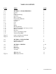
TABLE OF CONTENTS PARA. TITLE PAGE 1.0 1.1 1.2 1.3 1.4 1.5 1.6 1.7 1.8 1.9 1.10 1.11 1.12 1.13 1.14 1.15 1.16 1.
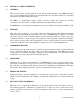
1.0 SECTION 1 - CHARACTERISTICS 1.1 GENERAL This section describes operating instructions and operational characteristics of the SM-2 Automatic Crew-overboard light. The information presented herewith is in conformance with U.S. Coast Guard Specification 46 CFR 161.010 and 161.110. The SM-2 is a lightweight, compact, battery operated, portable unit which uses modular construction for basic circuits to simplify maintenance and replacement procedures.
1.7 CONSTRUCTION The SM-2 Light essentially consists of a case with a battery, switch, electric circuit, flashlamp, globe, lanyard attachment flange, a mounting bracket, and a buoyant, non-absorbent unicellular polyfoam, used as filler material. 1.8 LANYARD The size, weight, and shape of the light are suitable for conveniently throwing overboard, while attached to a life ring buoy by means of a lanyard. A hole is provided in the bottom flange of the case for lanyard attachment. 1.
1.14 STROBOSCOPIC FLASHING LIGHT The SM-2 Flashing Light uses a capacitor discharge xenon flashtube and meets the following requirements. A. A completely sealed solid state circuit converts power from the battery and supplies it to the flashtube. B. A suitable capacitor discharge, xenon flashtube is provided which is compatible with the electronic flashing circuit and lens which will provide the required light output. The service life of this flashtube is rated for 5,000,000 flashes. C.
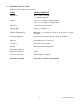
1.17 TECHNICAL DATA - SM-2 Pertinent Technical Data is listed below: ITEM CHARACTERISTICS Dimensions 13.65" (34.67 cm) length 4" (10.16 cm) diameter Weight 3 lbs, 4 oz. (1.474 Kg), including battery 1 lb, 13 oz. (.822 Kg), excluding battery Modules (1) completely sealed electronics Flashing Rate 60 times per minute ± 1 Flashing Light Intensity Minimum of 2 candelas per flash in all directions of upper hemisphere Power Requirement Standard 6.
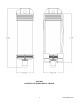
FIGURE 1 OUTLINE AND DIMENSIONAL SKETCH 7 Y1-03-0165 Rev.
FIGURE 2 INSTRUCTION PLATE LABEL 8 Y1-03-0165 Rev.
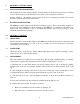
2. SECTION 2 - INSTALLATION 2.1 INSTALLATION PROCEDURES The installation procedure requires that the mounting bracket be securely fastened in any convenient location which would provide immediate access in the event of emergency situations. Suitable length ¼ - 20 stainless screws should be used for mounting the bracket. Screw heads should not protrude inside the bracket surface. 2.2 BATTERY INSTALLATION The SM-2 is normally shipped from the factory without a battery.
3. Inspect O-Ring seal for proper fit. Lubricate with silicone grease. F. Replace the battery by securing the two terminals to the battery posts. Assure tightness. NOTE: Connect black lead to center (-) post of battery. Connect red lead to outer (+) post of battery. G. Check for proper operation by holding the top cap assembly vertical (light lens up). The unit should flash about once each second. If the unit does not operate, check for proper battery connection. 3.
SM-2 PARTS LIST ITEM DESCRIPTION PART NUMBER 1 Case Assembly A3-06-2295 *2 Case A1-18-1878 *3 Washer, 3 each A1-05-0659-3 *4 Locking Swivel, 3 each A1-17-1283 5 Battery Pad, Foam A1-18-0773 6 Battery 6 Volt Lantern Type (See Tech. Data 2.17 for recommended battery) Not Included 7 Foam Filler A1-18-1877 8 O-Ring (Top Cap) A1-05-0001-64 9 Top Cap and Lens Tube Assembly 9021.1 10 Mounting Bracket 9438.
FIGURE 3 EXPLODED VIEW SM-2 12 Y1-03-0165 Rev.