PRODUCT SUPPORT MANUAL Y1-03-0180 Rev. A ThunderBird SSAS Ship Security Alert System FCC Type Accepted Model No. RLB-33S Product No. 2800 Owner Vessel Radio Call Sign ACR Electronics, Inc. 5757 Ravenswood Road Fort Lauderdale, Fl 33312 +1(954) 981-3333 • Fax +1 (954) 983-5087 www.acrelectronics.com Email: Info@acrelectronics.
* * * WARNING * * * THIS BEACON IS AUTHORIZED FOR USE ONLY DURING SITUATIONS WHERE THE SECURITY OF YOUR VESSEL IS UNDER THREAT OR HAS BEEN COMPROMISED AND POLICE ACTION IS REQUIRED DELIBERATE MISUSE MAY INCUR A SEVERE PENALTY ***Attention*** This beacon MUST be reprogrammed by an authorized ACR distributor prior to installation and use. Failure to do so will result in incorrect routing of a security alert.
Forward Congratulations and thank you for purchasing the ACR ThunderBird 406 MHz Ship Security Alert System (SSAS). The combination of superior design, high quality raw materials and quality controlled manufacturing produces a product that will perform for years to come. The Test Facility at ACR can reproduce some of the harshest environmental conditions known to man. This assures that the products we design and manufacture can stand up to the rigors found in a marine environment.
SECTION 1 - REGISTRATION AND PROGRAMMING YOUR 406 MHZ BEACONS 1.1 Programming This SSAS beacon is programmed with a serialized Unique Identifier Number (UIN). In order for a security alert to be routed properly, this beacon must be reprogrammed by an authorized ACR distributor before installation or use can occur. This beacon must be reprogrammed as follows: • With protocol code for SSAS • With the country code of the vessel’s flag state • With the vessel’s unique MMSI 1.
The information provided on the Registration Form is used only for rescue purposes. The Registration Form should be filled out and mailed immediately. Registration can be expedited by registering online or by faxing the registration form to Fax # (301) 568-8649. Registrations should be faxed in the event the Beacon is to be placed in immediate service and followed up with the mailing of the hard copy form.
SECTION 2 - FALSE ALARMS 2.1 Prevention of false alarms. There are a few precautions that should be taken to prevent false alarms: Do not transport Beacon within 1 meter (3.3ft) of a magnetic source. Do not mount Beacon within 1 meter (3.3ft) of a magnetic source. Do not mount remote switches where they can be confused with another switch. Do not mount beacon where it can get wet. Do not clean beacon with any liquid. 2.
SECTION 3 - INSTALLATION 3.1 Preparation 3.1.1 Parts included: Beacon/Mounting Bracket Assy Cross Dipole Antenna SMA Male Conn, RG-8/U Crimp Activation Switches Antenna Mount TNC Male Conn, RG-8/U Crimp Insulated Terminals, Crimp Qty: 1 Qty: 1 Qty: 1 Qty: 2 Qty: 1 Qty: 1 Qty: 4 PN: A3-06-2410-1 PN: 2810 PN: 2814 PN: 2820 PN: 2821 PN: 2633 PN: A1-05-0125-17 3.1.2 Tools Needed: Phillips screwdriver Drill RG-8/U Crimp tool Saw Solder Iron 3.1.
Also to be considered in selecting a location for installation is the harmful effect that certain corrosive vapors might have on the beacon. Under no circumstances should a location be selected for installation where the beacon would be jeopardized by any foreign articles being temporarily or permanently positioned during “at sea” or “in port” activities. Do not mount or store the beacon within 1 meter (3.
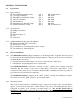
3.2.5 Connecting the beacon to a GPS receiver via the optical Interface (IR Transmitter) Your Beacon comes with a NMEA GPS Optical Interface cable (transmitter plug with lead wires) that should be connected to the ship’s GPS system. The IR transmitter plug attaches to your Beacon, via the keyed blue bezel on the top left of the beacon. The cable can be routed through the hole in the upper left corner of bracket.
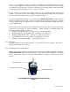
for 16 to 22 AWG wire for the connection to the mounting bracket. Other marine grade lugs (Not Supplied) can be used for different gauge wire. Because two wires are required to connect the switch to the mounting bracket, a two conductor cable is ideal. This makes routing the wire easier and provides additional strength. Activation button with recommended wire soldered to the switch Figure 2 3.3.
3.3.6 Switch installation verification To verify proper installation of the switches, the following procedure should be followed (requires two persons, preferably with 2-way radio communications): • • • • Perform this procedure with all connections made between the switches and the beacon. The beacon must be in OFF mode. Performing this test with the beacon in READY mode may result in a live transmission to the satellite system.
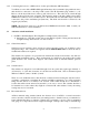
3.4.3 Antenna assembly The antenna is shipped with the four elements removed from the housing. Before using the antenna, these elements must be assembled to the antenna housing. For each element, assemble as follows: 1. Slide the grooved end of the element into a hole in the side of the housing until it stops 2. Install and tighten appropriate set screw through hole in the bottom housing using included wrench 3. Pull lightly on the element to ensure it is tightly secured 1. 3.4.4 2. 3.
Connect the male TNC cable assembly to the mating female TNC connector on antenna. Slide wire thru mounting bracket to connect to antenna Fasten TNC cable assembly to the mating female TNC connector on antenna Secure antenna to the mounting bracket Route cable to SSAS beacon as needed, making sure to adequately secure the cable. Provide a drip loop in the cable near the beacon to prevent water from running directly on to the beacon. Trim the cable to the appropriate length.
• • If the test burst was not received, the FPR-100 may be too far from the antenna. Repeat the test with the FPR-100 closer to the antenna. (Typically, an FPR-100 can receive a signal from the cross dipole at a maximum range of 100 ft. (30.5m). If the FPR-100 still does not receive the test burst, check all coaxial connections from the beacon to the antenna. SECTION 4 - OPERATION 4.1 General 4.1.1 The ThunderBird SSAS Beacon can only be activated manually while installed in the mounting bracket. 4.1.
4.4 Modes of operation 4.4.1 OFF Mode: The ThunderBird SSAS can not be activated when in OFF mode. The beacon is in OFF mode whenever the thumb switch is in the “Off” position (down to the front) as indicated by the “O” symbol displayed on the thumb switch. 4.4.2 READY Mode: The ThunderBird SSAS is capable of being activated when in READY mode.
Battery connection Plug 4.7 Full functional Self Test Please read all instructions before performing any of the tests. Be prepared to record data from the test. 4.7.1 The ThunderBird SSAS can be tested in or out of the release bracket. A Self Test is initiated by lifting the thumb switch to a vertical position and holding it in this position for at least one second. The initiation of the test is indicated by the simultaneous and brief lighting of the green and red LED's. The sequence of tests is: 1.
stored is accurate. This can be accomplished by two methods: First, by always leaving a properly functioning GPS receiver connected to the Beacon before activation. Second, by connecting a properly functioning GPS receiver with a valid position fix to the Beacon and allowing sufficient time for the Beacon to acquire valid position data from the GPS. This will take a nominal 20 minutes if old GPS position data is stored in the Beacon’s memory.
SECTION 5 - CARE AND MAINTENANCE 5.1 At least every ninety days, the mounting bracket, antenna and beacon should be inspected for deterioration and/or buildup that may affect the function of the beacon or it’s mounting. Also carefully inspect the beacon case for any visible cracks. Cracks may admit moisture, which could falsely activate the beacon or otherwise cause a malfunction. Any cracking observed should be immediately referred to ACR for evaluation, (1-800-432-0227 Ext. 112).
6.1.2 The message transmitted by the ThunderBird SSAS is unique for each SSAS, which provides identification of the transmitter through computer access of registration files maintained by the National Oceanic and Atmospheric Administration or other national authority. It is the user’s responsibility to fill out and mail the enclosed registration form to the appropriate agency of the country under which the vessel is registered.
6.2.5 The COSPAS-SARSAT System includes 36 LEOSAR LUT stations, 6 GEOSAR LUT stations and 19 Mission Control Centers that provide real-time as well as global-mode coverage for the Northern Hemisphere, while the Southern Hemisphere is presently served primarily by the global mode. Additional LUTs and MCCs are planned for installation in the near future both in the northern and southern hemispheres. The addition of the GEOSAR Satellite system greatly improves the reaction time for a security event.
SECTION 7 - AUTHORIZATIONS 7.1 Type Approvals 7.1.1 The ThunderBird SSAS meets the requirements of Federal Communications Commission (FCC) Part 80 and GMDSS. FCC ID: B66ACR-RLB-33S 7.1.2 COSPAS-SARSAT Type Approval Certification No.141 7.2 Characteristics 7.2.1 The ThunderBird SSAS is a floatable, battery operated unit. The beacon case, with its external antenna, is waterproof. The semiconductor circuits are mounted within the case assembly that also contains the battery power supply.
Size SSAS less Antenna 7.20” (18.29 cm) Material, SSAS High impact and UV resistant plastic Color Blue Weight 1.9 lbs. (862 g) Temperature Range Operating -25°C to +55°C Stowage -25°C TO +70°C 1 Leaves ACR with Serialized U.S. code but must be reprogrammed at an authorized ACR Service center with SSAS protocol code, the vessels Maritime MMSI and country code of the flag state before installing on a ship. USER / PROGRAMMING INTERFACE µP 406 MHz RF AMPLIFIER SSAS BLOCK DIAGRAM FIGURE 6 7.3.
* * * WARNING * * * THIS BEACON IS AUTHORIZED FOR USE ONLY DURING SITUATIONS WHERE THE SECURITY OF YOUR VESSEL IS UNDER THREAT OR HAS BEEN COMPROMISED AND POLICE ACTION IS REQUIRED COSPAS-SARSAT System Overview FIGURE 7 22 Y1-03-0180 Rev.
ACR THUNDERBIRD FIGURE 8 23 Y1-03-0180 Rev.
ANTENNA INSTALLATIONS FIGURE 9 24 Y1-03-0180 Rev.
INCH (mm) RECOMMENDED CABLE STRIPPING DIMENSIONS FOR TNC CONNECTOR FIGURE 10 INCH (mm) RECOMMENDED CABLE STRIPPING DIMENSIONS FOR SMA CONNECTOR FIGURE 11 25 Y1-03-0180 Rev.
FIGURE 12 SSAS SYSTEM BLOCK DIAGRAM 26 Y1-03-0180 Rev.
INSTALLATION CHECK LIST Please Review to ensure you have properly installed this SSAS beacon: Installed the beacon and bracket on a flat vertical surface in a discreet location. (Paragraph 3.2) Installed the activation switches. (Minimum of two.) One must be on the navigation bridge. Switches shall not be labeled. (Paragraph 3.3.4) Connected switch wire to switches and terminal block on the top of the mounting bracket. Route wire appropriately. (Paragraph 3.3.