Acronis Storage 2.
Copyright Statement Acronis International GmbH, 2002-2016. All rights reserved. ”Acronis” and ”Acronis Secure Zone” are registered trademarks of Acronis International GmbH. ”Acronis Compute with Confidence”, ”Acronis Startup Recovery Manager”, ”Acronis Active Restore”, ”Acronis Instant Restore” and the Acronis logo are trademarks of Acronis International GmbH. Linux is a registered trademark of Linus Torvalds. VMware and VMware Ready are trademarks and/or registered trademarks of VMware, Inc.
Contents 1. Introduction . . . . . . . . . . . . . . . . . . . . . . . . . . . . . . . . . . . . . . . . . . . . . . . . . . . . . 1 1.1 About This Guide . . . . . . . . . . . . . . . . . . . . . . . . . . . . . . . . . . . . . . . . . . . . . . . 1 1.2 About Acronis Storage . . . . . . . . . . . . . . . . . . . . . . . . . . . . . . . . . . . . . . . . . . . . 2 2. Accessing Storage Clusters via iSCSI . . . . . . . . . . . . . . . . . . . . . . . . . . . . . . . . . . . . . . 3 2.
3.1 About Object Storage . . . . . . . . . . . . . . . . . . . . . . . . . . . . . . . . . . . . . . . . . . . . 14 3.1.1 Object Storage Infrastructure Overview . . . . . . . . . . . . . . . . . . . . . . . . . . . . . 15 3.1.2 Object Storage Overview . . . . . . . . . . . . . . . . . . . . . . . . . . . . . . . . . . . . . 17 3.1.3 3.1.4 3.1.2.1 Multipart Uploads . . . . . . . . . . . . . . . . . . . . . . . . . . . . . . . . . . . 17 3.1.2.2 Object Storage Interaction with a Storage Cluster . .
3.6 3.5.1 Bucket and Key Naming Policies . . . . . . . . . . . . . . . . . . . . . . . . . . . . . . . . . 36 3.5.2 Improving Performance of PUT Operations . . . . . . . . . . . . . . . . . . . . . . . . . . 36 Supported Amazon S3 Features . . . . . . . . . . . . . . . . . . . . . . . . . . . . . . . . . . . . . . 36 3.6.1 Supported Amazon S3 REST Operations . . . . . . . . . . . . . . . . . . . . . . . . . . . . 36 3.6.2 Supported Amazon Request Headers . . . . . . . . . . . . . . . . . . . . . . .
CHAPTER 1 Introduction This chapter provides basic information about this guide and Acronis Storage. 1.1 About This Guide This guide complements the documentation on managing Acronis Storage via the web-based management panel. It is recommended to manage Acronis Storage via the management panel. If you have it installed, consider the command-line tools secondary and use them with caution.
Chapter 1. Introduction 1.2 About Acronis Storage Acronis Storage is a software-defined storage solution that allows you to quickly and easily transform low-cost commodity storage hardware and network equipment into protected enterprise-grade storage like SAN or NAS. Acronis Storage is optimized for storing large amounts of data and provides data redundancy (replication and erasure coding), high availability, self-healing, and storage sharing.
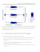
CHAPTER 2 Accessing Storage Clusters via iSCSI Acronis Storage allows you to export cluster disk space to external operating systems and third-party virtualization solutions in the form of LUN block devices over iSCSI in a SAN-like manner. In Acronis Storage, you can create and run multiple iSCSI targets per cluster node. In turn, each iSCSI target can have multiple LUNs (virtual disks). At any given moment, each iSCSI target runs on a single node.
Chapter 2. Accessing Storage Clusters via iSCSI In this example, two Acronis Storage nodes host one iSCSI target each, while the third hosts two iSCSI targets. Each node connects to two networks: internal for storage cluster communication and external (in relation to the storage cluster) for iSCSI exporting. Each iSCSI target has a unique static IP address from a dedicated subnet of the datacenter network. 2.
2.2. Creating iSCSI Targets ISCSI_ROOT=/vstorage/stor1/iscsi You are now ready to create iSCSI targets in your Acronis Storage cluster. 2.2 Creating iSCSI Targets Note: 1. Each iSCSI target must be assigned at least one unique IP address from DC network’s static pool. 2. The name of each iSCSI target must be unique in the Acronis Storage cluster. 3. Acronis Storage iSCSI targets support persistent reservations to allow iSCSI initiators obtain exclusive access to the specified target’s LUNs.
Chapter 2. Accessing Storage Clusters via iSCSI Host: fefacc38a2f140ca LUN: 1, Size: 102400M, Used: 1M, Online: Yes For information about the command output, see Listing iSCSI Targets on page 6. iSCSI initiators can now access the target iqn.2014-04.com.vstorage:test1 via the portal 192.168.10.100. 2.2.1 Performance Tips • Spread iSCSI targets evenly across nodes in the cluster. For example, ten nodes with one iSCSI target per each will perform better than a single node with ten iSCSI targets on it.
2.4. Transferring iSCSI Targets between Nodes Item Description Target Unique alphanumeric name of the iSCSI target. Portals Target’s IP address(es). Status Target’s current state. • running: target is running and ready for use (for local targets). • stopped: target is stopped (for local targets). • service failed: the iSCSI service is down (for local targets). • remote: target is registered on a different node. • unregistered: target is not registered on any node in the Acronis Storage cluster.
Chapter 2. Accessing Storage Clusters via iSCSI # vstorage-iscsi register -t iqn.2014-04.com.vstorage:test1 2.5 Stopping iSCSI Targets To stop an iSCSI target to which no initiators are connected, use the vstorage-iscsi stop command. For example, for the target iqn.2014-04.com.vstorage:test1: # vstorage-iscsi stop -t iqn.2014-04.com.vstorage:test1 If one or more iSCSI initiators are still connected to the target, you will be informed as follows: # vstorage-iscsi stop -t iqn.2014-04.com.
2.7. Configuring Multipath I/O for iSCSI Targets # vstorage-iscsi delete -t iqn.2014-04.com.vstorage:test1 --force 2.7 Configuring Multipath I/O for iSCSI Targets Multipath I/O is a technique called to increase fault tolerance and performance by establishing multiple paths to the same iSCSI target. The figure below shows a typical multipath-enabled setup for exporting Acronis Storage disk space over iSCSI. In this example, each iSCSI target is assigned static IP addresses from two datacenter subnets.
Chapter 2. Accessing Storage Clusters via iSCSI 2.8 Managing iSCSI Users You can restrict access to iSCSI targets by means of CHAP authentication. To make use of CHAP authentication, you need to: 1. Create a CHAP account. 2. Create an iSCSI target bound to this CHAP account. These actions are described in detail in the following subsections. 2.8.1 Creating CHAP Accounts for iSCSI Targets To create a CHAP account, use the vstorage-iscsi account-create command.
2.9. Managing LUN Snapshots 2.8.4 Listing CHAP Accounts and Their iSCSI Targets To list existing CHAP accounts, use the vstorage-iscsi account-list command. For example: # vstorage-iscsi account-list user1 To list iSCSI targets assigned to a specific CHAP account, use the vstorage-iscsi account-list command with the -u option. For example, to list iSCSI targets assigned to the CHAP account user1: # vstorage-iscsi account-list -u user1 iqn.2014-04.com.vstorage:test1 2.
Chapter 2. Accessing Storage Clusters via iSCSI In the output above, the asterisk in the column C indicates the current snapshot, while the column PARENT_UUID shows snapshot dependency or history. 2.9.3 Switching Between LUN Snapshots To switch to the specified LUN snapshot, use the vstorage-iscsi snapshot-switch command. For example: # vstorage-iscsi snapshot-switch -u a1f54314-bc06-40c6-a587-965feb9d85bb After you switch to a snapshot, the current LUN image will be removed.
2.9. Managing LUN Snapshots 2. Deleting a snapshot that has multiple children is currently not supported.
CHAPTER 3 Accessing Storage Clusters via S3 Protocol Acronis Storage can export data via an Amazon S3-like API, enabling service providers to: • run S3-based services in their Acronis Storage infrastructures, • sell S3-based storage-as-a-service to customers along with Acronis Storage. The support for S3 expands the functionality of Acronis Storage and requires a working Acronis Storage cluster. 3.
3.1. About Object Storage Another feature of object storage is eventual consistency. Eventual consistency does not guarantee that reads are to return the new state after the write has been completed. Readers can observe the old state for an undefined period of time until the write is propagated to all the replicas (copies). This is very important for storage availability as geographically distant data centers may not be able to perform data update synchronously (e.g.
Chapter 3. Accessing Storage Clusters via S3 Protocol • An object server stores actual object data received from S3 gateway. The data is packed into special containers to achieve high performance. The containers are redundant, you can specify the redundancy mode while configuring object storage. An object server also stores its own data in block storage with built-in high availability. • A name server stores object metadata received from S3 gateway.
3.1. About Object Storage storage services run on hosts, no virtual environments (and hence licenses) are required for object storage. For more information, see Object Storage Components on page 18. 3.1.2 Object Storage Overview In terms of S3 object storage, a file is an object. Object servers store each object loaded via the S3 API as a pair of entities: • Object names and associated object metadata stored on an NS.
Chapter 3. Accessing Storage Clusters via S3 Protocol 3.1.3 Object Storage Components This section offers more detail on S3 storage components: gateways, object servers, and name servers; and describes S3 management tools and service buckets. 3.1.3.1 Gateway A gateway performs the following functions: • Receives S3 requests from the web server (via NGINX and FastCGI). • Parses S3 packets and validates S3 requests (checks fields of a request and XML documents in its body). • Authenticates S3 users.
3.1. About Object Storage 3.1.3.2 Name Server A name server performs the following functions: • Stores object names and metadata. • Provides the API for pasting, deleting, listing object names and changing object metadata. Name server consists of data (i.e. object metadata), object change log, an asynchronous garbage collector, and asynchronous handlers of incoming requests from different system components.
Chapter 3. Accessing Storage Clusters via S3 Protocol a free/dirty bit mask. The region’s data is stored in the same file with an object’s B-tree. It provides atomicity during the block’s allocation and deallocation. Every block in the region contains a header and object’s data. The header stores the ID of an object to which the data belong. The ID is required for a pool-level defragmentation algorithm that does not have an access to the object’s B-tree.
3.1. About Object Storage • Names with a /tmp/ prefix. Correspond to information on operations that consist of several atomic alterations of objects in the storage. These names are necessary in case the operation fails. 3.1.4 Data Interchange In object storage, every service has a 64-bit unique identifier. At the same time, every object has a unique name. The directory part of an object’s name determines a name server to store it, and the full object’s name—an object server to store the object’s data.
Chapter 3. Accessing Storage Clusters via S3 Protocol 3.1.5 Operations on Objects This section familiarizes you with operations S3 storage processes: operations requests; create, read, and delete operations. 3.1.5.1 Operation Requests To create, delete, read an object or alter its data, S3 object storage must first request one if these operations and then perform it. The overall process of requesting and performing an operation consists of the following: 1. Requesting user authentication data.
3.2. Deploying Object Storage 3.1.5.3 Read Operation To fulfill an S3 read request, gateway determines an appropriate name server’s identifier based on the name of a directory and corresponding object server’s identifier based on the object’s full name. To perform a read operation, gateway sends the following requests: 1. Request with a read operation code to an appropriate name server. A response to it contains a link to an object. 2.
Chapter 3. Accessing Storage Clusters via S3 Protocol To set up object storage services, do the following: 1. Plan the S3 network. Like a storage cluster, an S3 cluster needs two networks: • An internal network in which NS, OS, and GW will interact. These services will generate traffic similar in amount to the total (incoming and outgoing) S3 user traffic. If this is not going to be much, it is reasonable to use the same internal network for both object storage and Acronis Storage.
3.2. Deploying Object Storage • An external (public) network through which end users will access the S3 storage. Standard HTTP and HTTPS ports must be open in this network. An object storage cluster is almost completely independent on base block storage (like all access points, including virtual environments and iSCSI). Object and name servers keep their data in the Acronis Storage cluster in the same way as virtual environments, iSCSI, and other services do.
Chapter 3. Accessing Storage Clusters via S3 Protocol directory in the cluster with object storage service files). If the first configuration service fails (and the ostor-ctl get-config command stops working), replace the IP address in ///control/name with that of a node running a healthy configuration service (created on the next step). 5. Launch the configuration service. # systemctl start ostor-cfgd.service # systemctl enable ostor-cfgd.service 6.
3.2. Deploying Object Storage (round-robin) manner. 8. Add nodes where object storage services will run to the configuration. To do this run the ostor-ctl add-host command on every such node: # ostor-ctl add-host -r /var/lib/ostor/configuration --hostname --roles OBJ You will need to provide the object storage password set on step 3. 9. Create a new S3 volume with the desired number of NS and OS: # ostor-ctl add-vol --type OBJ -s --os-count \ --ns-count --vstora
Chapter 3. Accessing Storage Clusters via S3 Protocol manner. However, manual assignment is required if a new host has been added to the configuration, or if the current configuration is not optimized (for details, see Manually Binding Services to Nodes on page 29. You can check the current binding configuration with the ostor-ctl agent-status command.
3.2. Deploying Object Storage # systemctl start nginx.service # systemctl enable nginx.service The object storage is deployed. Now you can add S3 users with the ostor-s3-admin tool. For example: # ostor-s3-admin create-user -e user@email.com Created user: email=user@email.
Chapter 3.
3.3. Managing S3 Users 3.3.1 Adding S3 Users You can generate a unique random S3 user ID and an access key pair (S3 Access Key ID, S3 Secret Access Key) using the ostor-s3-admin create-user command. You need to specify a user email. For example: # ostor-s3-admin create-user -e user@email.com -V 0100000000000002 UserEmail:user@email.
Chapter 3. Accessing Storage Clusters via S3 Protocol 3.3.3 Querying S3 User Information To display information about the specified user, use the ostor-s3-admin query-user-info command. You need to specify either the user email (-e) or S3 ID (-i). For example: # ostor-s3-admin query-user-info -e user@email.com -V 0100000000000002 Query user: user id=d866d9d114cc3d20, user email=user@email.
3.4. Managing S3 Buckets Note: It is recommended to periodically revoke old and generate new access key pairs. 3.3.7 Revoking S3 User Access Key Pairs You can revoke the specified access key pair of the specified user with the ostor-s3-admin revoke-access-key command. You need to specify the access key in the key pair you want to delete as well as the user email or S3 ID. For example: # ostor-s3-admin revoke-access-key -e user@email.
Chapter 3. Accessing Storage Clusters via S3 Protocol 3.4.1 Listing S3 Bucket Contents You can list bucket contents with a web browser. To do this, visit the URL that consists of the external DNS name for the S3 endpoint that you specified when creating the S3 cluster and the bucket name. For example, mys3storage.example.com/mybucket or mybucket.mys3storage.example.com (depending on DNS configuration).
3.5. Best Practices for Using Object Storage 3.4.3 Querying S3 Bucket Information You can query bucket metadata information and ACL with the ostor-s3-admin query-bucket-info command. For example, for bucket1: # ostor-s3-admin query-bucket-info -b bucket1 -V 0100000000000002 BUCKET OWNER CREATION_DATE VERSIONING TOTAL_SIZE bucket1 d339edcf885eeafc 2017-12-21T12:42:46.000Z none 0 ACL: d339edcf885eeafc: FULL_CONTROL 3.4.
Chapter 3. Accessing Storage Clusters via S3 Protocol 3.5.1 Bucket and Key Naming Policies It is recommended to use bucket names that comply with DNS naming conventions: • can be from 3 to 63 characters long, • must start and end with a lowercase letter or number, • can contain lowercase letters, numbers, periods (.), hyphens (-), and underscores (_), • can be a series of valid name parts (described previously) separated by periods.
3.6.
Chapter 3. Accessing Storage Clusters via S3 Protocol Operation Supported Initiate Multipart Upload Yes List Parts Yes Upload Part Yes Upload Part - Copy No DELETE/GET/PUT Object tagging No GET Object torrent No OPTIONS Object No POST Object restore No Note: For more information on Amazon S3 REST operations, see Amazon S3 REST API documentation. 3.6.
3.6. Supported Amazon S3 Features Note: For more information on Amazon S3 REST request headers, see the Amazon S3 REST API documentation. 3.6.
Chapter 3. Accessing Storage Clusters via S3 Protocol • Message • RequestId • Resource The following Amazon S3 REST error response headers are not supported: • RequestId (not used) • Resource Note: For more information on Amazon S3 REST response headers, see the Amazon S3 REST API documentation. 3.6.5 Supported Authentication Scheme and Methods The following authentication scheme is supported by the Acronis Storage implementation of the Amazon S3 protocol: • Signature Version 2. • Signature Version 4.
CHAPTER 4 Monitoring Storage Cluster Monitoring the storage cluster is very important because it allows you to check the status and health of all computers in the cluster and react as necessary. The main command for monitoring is vstorage -c top. It invokes a text user interface that you can control with keys (press h for help). 4.
Chapter 4. Monitoring Storage Cluster The command above shows detailed information about the stor1 cluster. The general parameters (highlighted in red) are explained in the table below. Parameter Description Cluster Overall status of the cluster: • healthy. All chunk servers in the cluster are active. • unknown. There is not enough information about the cluster state (e.g., because the master MDS server was elected a while ago). • degraded. Some of the chunk servers in the cluster are inactive.
4.1. Monitoring General Storage Cluster Parameters Parameter Description Space Amount of disk space in the cluster: • free. Free physical disk space in the cluster. • allocatable. Amount of logical disk space available to clients. Allocatable disk space is calculated on the basis of the current replication parameters and free disk space on chunk servers. It may also be limited by license.
Chapter 4. Monitoring Storage Cluster 4.2 Monitoring Metadata Servers MDS servers are a critical component of any storage cluster, and monitoring the health and state of MDS servers is a very critical task. To monitor MDS servers, use the vstorage -c top command, for example: The command above shows detailed information about the stor1 cluster.
4.3. Monitoring Chunk Servers Parameter Description UPTIME Time elapsed since the last MDS server start. HOST MDS server hostname or IP address. 4.3 Monitoring Chunk Servers By monitoring chunk servers, you can keep track of the disk space available in a storage cluster. To monitor chunk servers, use the vstorage -c top command, for example: The command above shows detailed information about the stor1 cluster.
Chapter 4. Monitoring Storage Cluster Parameter Description STATUS Chunk server status: • active. The chunk server is up and running. • Inactive. The chunk server is temporarily unavailable. A chunk server is marked as inactive during its first 5 minutes of inactivity. • offline. The chunk server is inactive for more than 5 minutes. After the chunk server goes offline, the cluster starts replicating data to restore the chunks that were stored on the affected chunk server. • dropped.
4.3. Monitoring Chunk Servers Cluster 'stor1': healthy Space: [OK] allocatable 180GB of 200GB, free 1.6TB of 1.7TB ... In this command output: • 1.7TB is the total disk space in the stor1 cluster. The total disk space is calculated on the basis of used and free disk space on all partitions in the cluster. Used disk space includes the space occupied by all data chunks and their replicas plus the space occupied by any other files stored on the cluster partitions.
Chapter 4. Monitoring Storage Cluster used for storing user data. Once this space runs out, no data can be written to the cluster. To better understand how allocatable disk space is calculated, let us consider the following example: • The cluster has 3 chunk servers. The first chunk server has 200 GB of disk space, the second one — 500 GB, and the third one — 1 TB.
4.3. Monitoring Chunk Servers # vstorage set-attr -R /vstorage/stor1 replicas=2:1 # vstorage -c stor1 top connected to MDS#1 Cluster 'stor1': healthy Space: [OK] allocatable 680GB of 700GB, free 1.6TB of 1.7TB ... The available disk space has increased because now only 2 replicas are created for each data chunk and new chunks can be made even if the smallest chunk server runs out of space (in this case, replicas will be stored on a bigger chunk server).
Chapter 4. Monitoring Storage Cluster Status Description replicating Percentage of chunks which are being replicated. Write operations on such chunks are frozen until replication ends. offline Percentage of chunks all replicas of which are offline. Such chunks are completely inaccessible for the cluster and cannot be replicated, read from or written to. All requests to an offline chunk are frozen until a CS that stores that chunk’s replica goes online.
4.4. Monitoring Clients Status Description overcommitted Percentage of chunks that have more replicas than normal. Usually these chunks appear after the normal number of replicas has been lowered or a lot of data has been deleted. Extra replicas are eventually dropped, however, this process may slow down during replication. deleting Percentage of chunks queued for deletion. unique Percentage of chunks that do not have replicas. 4.
Chapter 4. Monitoring Storage Cluster Parameter Description CLID Client identifier (ID). LEASES Average number of files opened for reading/writing by the client and not yet closed, for the last 20 seconds. READ Average rate, in bytes per second, at which the client reads data, for the last 20 seconds. WRITE Average rate, in bytes per second, at which the client writes data, for the last 20 seconds. RD_OPS Average number of read operations per second the client made, for the last 20 seconds.
4.5. Monitoring Physical Disks If the SMART warning message is shown in the main table, one of the physical disks is in pre-failure condition according to S.M.A.R.T. Press d to switch to the disks table to see more details. For example: The disks table shows the following parameters: Parameter Description DISK Disk name assigned by operating system.
Chapter 4. Monitoring Storage Cluster Parameter Description SMART Disk’s S.M.A.R.T. status: • OK: The disk is healthy. • Warn: The disk is in pre-failure condition. Pre-failure condition means that at least one of these S.M.A.R.T. counters is nonzero: • Reallocated Sector Count • Reallocated Event Count • Current Pending Sector Count • Offline Uncorrectable TEMP Disk temperature in Celsius. CAPACITY Disk capacity. SERIAL Disk serial number. MODEL Disk model. HOST Disk’s host address.
4.6. Monitoring Event Logs The command above shows the latest events in the stor1 cluster. The information on events (highlighted in red) is given in the table with the following columns: Column Description TIME Time when the event happened. SYS Component of the cluster where the event happened (e.g., MDS for an MDS server or JRN for local journal). SEV Event severity. MESSAGE Event description. 4.6.
Chapter 4. Monitoring Storage Cluster Event Severity Description MDS# (:) lags JRN err Generated by the MDS master server when it detects behind for more than 1000 that MDS# is stale. rounds This message may indicate that some MDS server is very slow and lags behind. MDS# (:) JRN err didn’t accept commits for M sec Generated by the MDS master server if MDS# did not accept commits for M seconds. MDS# gets marked as stale.
4.6. Monitoring Event Logs Event Severity Description The cluster is degraded with N MDS warn Generated when the cluster status changes to de- active, M inactive, K offline CS graded or when a new MDS master server is elected. This message indicates that some chunk servers in the cluster are • inactive (do not send any registration messages) or • offline (are inactive for a period longer than mds.wd.offline_tout = 5min (by default)).
Chapter 4. Monitoring Storage Cluster Event Severity Description CS# has not registered dur- MDS warn Generated when the chunk server CS# has been ing the last T sec and is marked unavailable for a while. In this case, the chunk server as inactive/offline first gets marked as inactive. After 5 minutes, the state is changed to offline, which starts the automatic replication of data to restore the replicas that were stored on the offline chunk server.
4.7. Monitoring the Status of Replication Parameters License: PCSS.02444715.0000 is ACTIVE, 6399TB capacity Replication: 3 norm, 2 limit Chunks: [OK] 431 (100%) healthy, 0 (0%) degraded, 0 (0%) urgent, 0 (0%) blocked, 0 (0%) offline, 0 (0%) replicating, 0 (0%) overcommitted, 0 (0%) deleting, 0 (0%) void ... 3. Check the Chunks field for the following: • When decreasing the replication parameters, look for chunks that are in the overcommitted or deleting state.
CHAPTER 5 Managing Storage Cluster Security This chapter describes some situations that may affect your cluster security. 5.1 Security Considerations This section describes the security limitations you should keep in mind when deploying a storage cluster. Traffic sniffing Acronis Storage does not protect you from traffic sniffing. Anyone who has access to your network can capture and analyze the data being sent and received through your network.
5.2. Securing Node Communication in the Storage Cluster 5.2 Securing Node Communication in the Storage Cluster A storage cluster can contain three types of servers: • MDS servers • chunk servers • clients During cluster operation, the servers communicate with each other. To secure their communication, you should keep all servers on an isolated internal network. The process of deploying such a setup is as follows: 1.
Chapter 5. Managing Storage Cluster Security The specified address will then be used for MDS interconnection and intercommunication with the other servers in the cluster. 2. Set up a chunk server: # vstorage -c Cluster-Name make-cs -r CS-Directory Once it is created, the chunk server connects to the MDS server and binds to the IP address it uses to establish the connection.
5.3. Password-based Authentication command to authenticate them. During authentication, you use the password you set when creating the first MDS server. 3. Acronis Storage compares the provided password with the one stored on the first MDS server, and if the passwords match, successfully authenticates the server. For each physical server, authentication is a one-time process.
CHAPTER 6 Maximizing Storage Cluster Performance This chapter describes recommendations for maximizing the performance of your storage cluster. Note: Also consider updating hardware nodes in the cluster. 6.1 Carrying Out Performance Benchmarking When testing the performance of a storage cluster and comparing it with third-party setups: • Compare configurations with similar redundancy levels.
6.2. Checking Data Flushing 6.2 Checking Data Flushing Before creating the cluster, you are recommended to check that all storage devices (hard disk drives, solid disk drives, RAIDs, etc.) you plan to include in your cluster can successfully flush data to disk when the server power goes off unexpectedly. Doing so will help you detect possible problems with devices that may lose data stored in their cache in the event of a power failure.
Chapter 6. Maximizing Storage Cluster Performance • -s vstorage1.example.com is the hostname of the computer where the vstorage-hwflush-check server is running. • -d /vstorage/stor1-ssd/test defines the directory to use for testing data flushing. During its execution, the client creates a file in this directory and writes data blocks to it. • -t 50 sets the number of threads for the client to write data to disk. Each thread has its own file and counter. You can increase the number of threads (max.
6.3. Using 1 GbE and 10 GbE Networks continue with all remaining devices you plan to use in the cluster. 6.3 Using 1 GbE and 10 GbE Networks 1 Gbit/s Ethernet networks can deliver 110-120 MB/s, which is close to a single drive performance on sequential I/O. Since several drives on a single server can deliver higher throughput than a single 1 Gbit/s Ethernet link, networking may become a bottleneck.
Chapter 6. Maximizing Storage Cluster Performance 9000-byte jumbo frames). Such settings require switch configuration and often lead to human errors. 10 Gbit/s network adapters, on the other hand, need to be configured to use jumbo frames to achieve full performance. 3. For maximum efficiency, use the balance-xor bonding mode with the layer3+4 hash policy. If you want to use the 802.3ad bonding mode, also configure your switch to use the layer3+4 hash policy. 6.
6.5. Improving High-Capacity HDD Performance Note: 1. Make sure to enter the correct values in the IPADDR and PREFIX lines. 2. The balance-xor mode is recommended, because it offers both fault tolerance and better performance. For more details, see the documents listed below. 3. Make sure the configuration file of each Ethernet interface you want to bond (e.g.
Chapter 6. Maximizing Storage Cluster Performance The typical reasons of poor performance with 4KB sector HDDs are: 1. Host OS file system unaligned on the 4KB boundary. The make-cs command tries to detect and report such issues to the administrator in advance, but be aware that the fdisk utility is not recommended for partitioning HDDs. You should use parted instead. 2. Unaligned writes (e.g., 1KB) performed by guest OS.
6.6. Disabling Inter-Tier Data Allocation disable automatic data migration between tiers after making sure that each tier have enough free space. Execute the following command on any cluster node: # vstorage -c cluster1 set-config mds.alloc.