Acronis Storage 2.
Copyright Statement Acronis International GmbH, 2002-2016. All rights reserved. ”Acronis” and ”Acronis Secure Zone” are registered trademarks of Acronis International GmbH. ”Acronis Compute with Confidence”, ”Acronis Startup Recovery Manager”, ”Acronis Active Restore”, ”Acronis Instant Restore” and the Acronis logo are trademarks of Acronis International GmbH. Linux is a registered trademark of Linus Torvalds. VMware and VMware Ready are trademarks and/or registered trademarks of VMware, Inc.
Contents 1. Introduction . . . . . . . . . . . . . . . . . . . . . . . . . . . . . . . . . . . . . . . . . . . . . . . . . . . . . 1 1.1 About Acronis Storage . . . . . . . . . . . . . . . . . . . . . . . . . . . . . . . . . . . . . . . . . . . . 1 1.2 Deployment Overview . . . . . . . . . . . . . . . . . . . . . . . . . . . . . . . . . . . . . . . . . . . . 1 2. Planning Acronis Storage Infrastructure . . . . . . . . . . . . . . . . . . . . . . . . . . . . . . . . . . . 3 2.1 2.
2.2.6 2.3 2.4 Raw Disk Space Considerations . . . . . . . . . . . . . . . . . . . . . . . . . . . . . . . . . 18 Planning Network . . . . . . . . . . . . . . . . . . . . . . . . . . . . . . . . . . . . . . . . . . . . . . . 18 2.3.1 General Network Requirements . . . . . . . . . . . . . . . . . . . . . . . . . . . . . . . . . 19 2.3.2 Network Limitations . . . . . . . . . . . . . . . . . . . . . . . . . . . . . . . . . . . . . . . . 19 2.3.3 Per-Node Network Requirements . . . . . . . . . . . . . .
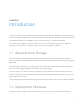
CHAPTER 1 Introduction To support the growing demand for both high performance and high data availability, modern data centers need a fast, flexible storage solution. Existing solutions, however, are often difficult to manage and maintain, or not flexible enough (e.g., local RAID arrays), or too expensive (e.g., storage area networks). Acronis Storage is designed to solve these issues. It can run on commodity hardware, so no significant infrastructure investments are needed.
Chapter 1. Introduction 1. Plan the infrastructure. 2. Install and configure Acronis Storage on each server in the planned infrastructure. 3. Create the storage cluster. 4. Set up data export for the cluster. 5. Populate the cluster with user data.
CHAPTER 2 Planning Acronis Storage Infrastructure To plan your Acronis Storage infrastructure, you will need to decide on the hardware configuration of each server, plan the Acronis Storage networks, decide on the redundancy method (and mode) to use, and decide which data will be kept on which storage tier. Information in this chapter is meant to help you complete all of these tasks. 2.
Chapter 2. Planning Acronis Storage Infrastructure • S3 name service (NS) • S3 object service (OS) • Admin panel • SSH • supplementary roles: • management, • SSD cache, • system Any server in the cluster can be assigned a combination of storage, metadata, and network roles. For example, a single server can be an S3 access point, an iSCSI access point, and a storage node at once. Each cluster also requires that a web-based admin panel be installed on one (and only one) of the nodes.
2.1. Understanding Acronis Storage Architecture controlling the cluster. 2.1.3 Network Roles (Storage Access Points) Storage access points enable you to access data stored in storage clusters via the standard iSCSI and S3 protocols and use the clusters as backend storage for Acronis Backup Cloud. To benefit from high availability, access points should be set up on multiple node.
Chapter 2. Planning Acronis Storage Infrastructure operations in the cluster by two and more times. System One disk per node that is reserved for the operating system and unavailable for data storage. 2.2 Planning Node Hardware Configurations Acronis Storage works on top of commodity hardware, so you can create a cluster from regular servers, disks, and network cards. Still, to achieve the optimal performance, a number of requirements must be met and a number of recommendations should be followed. 2.2.
2.2. Planning Node Hardware Configurations Type Minimal Recommended Sample configu- Intel Xeon E5-2620V2, 32GB, 2xST1000NM0033, ration 32xST6000NM0024, 2xMegaRAID SAS 9271/9201, Intel X540-T2, Intel P3700 800GB 2.2.2 Hardware Recommendations The following recommendations explain the benefits added by specific hardware in the hardware requirements table and are meant to help you configure the cluster hardware in an optimal way: 2.2.2.
Chapter 2. Planning Acronis Storage Infrastructure Note: 1. These considerations only apply if failure domain is host. 2. The speed of rebuilding in the replication mode does not depend on the number of nodes in the cluster. 3. Acronis Storage supports hundreds of disks per node. If you plan to use more than 36 disks per node, contact sales engineers who will help you design a more efficient cluster. 2.2.2.2 General Hardware Recommendations • At least five nodes are required for a production environment.
2.2. Planning Node Hardware Configurations 2.2.2.3 Storage Hardware Recommendations • It is possible to use disks of different size in the same cluster. However, keep in mind that, given the same IOPS, smaller disks will offer higher performance per terabyte of data compared to bigger disks. It is recommended to group disks with the same IOPS per terabyte in the same tier. • Using the recommended SSD models may help you avoid loss of data.
Chapter 2. Planning Acronis Storage Infrastructure • If capacity is the main goal and you need to store non-frequently accessed data, choose SATA disks over SAS ones. If performance is the main goal, choose SAS disks over SATA ones. • The more disks per node the lower the CAPEX. As an example, a cluster created from ten nodes with two disks in each will be less expensive than a cluster created from twenty nodes with one disk in each.
2.2. Planning Node Hardware Configurations • For maximum sequential I/O performance, use one 1Gbit/s link per each hard drive, or one 10Gbit/s link per node. Even though I/O operations are most often random in real-life scenarios, sequential I/O is important in backup scenarios. • For maximum overall performance, use one 10 Gbit/s link per node (or two bonded for high network availability). • It is not recommended to configure 1 Gbit/s network adapters to use non-default MTUs (e.g., 9000-byte jumbo frames).
Chapter 2. Planning Acronis Storage Infrastructure • Thin provisioning is always enabled for all data and cannot be configured otherwise. Note: For network limitations, see Network Limitations on page 19. 2.2.
2.2. Planning Node Hardware Configurations can replicate the data among them. If the node is a virtual machine, make sure that this VM is made highly available by the solution it runs on. Acronis Backup Gateway works with the local object storage in the staging mode. It means that the data to be replicated, migrated, or uploaded to a public cloud is first stored locally and only then sent to the destination.
Chapter 2. Planning Acronis Storage Infrastructure 2.2.5.1 HDD Only This basic configuration requires a dedicated disk for each metadata server. Nodes 1-5 (base) Disk No. Disk Type Disk Role(s) 1 HDD System 2 HDD MDS 3 HDD CS HDD CS Disk No. Disk Type Disk Role(s) 1 HDD System 2 HDD CS 3 HDD CS HDD CS ... N Nodes 6+ (extension) ... N 2.2.5.2 HDD + System SSD (No Cache) This configuration is good for creating capacity-oriented clusters. Nodes 1-5 (base) Disk No.
2.2. Planning Node Hardware Configurations Disk No. Disk Type Disk Role(s) 1 SSD System 2 HDD CS 3 HDD CS HDD CS ... N 2.2.5.3 HDD + SSD This configuration is good for creating performance-oriented clusters. Nodes 1-5 (base) Disk No. Disk Type Disk Role(s) 1 HDD System 2 SSD MDS, cache 3 HDD CS HDD CS Disk No. Disk Type Disk Role(s) 1 HDD System 2 SSD Cache 3 HDD CS HDD CS ... N Nodes 6+ (extension) ... N 2.2.5.
Chapter 2. Planning Acronis Storage Infrastructure the cluster. • If you use the erasure coding redundancy scheme, each erasure coding file, e.g., a single VM’s or container’s HDD disk, will get up to 2K sustainable IOPS. That is, a user working inside a VM or container will have up to 2K sustainable IOPS per virtual HDD at their disposal. Multiple VMs and containers on a node can utilize more IOPS, up to the client’s limit.
2.2. Planning Node Hardware Configurations Disk No. Disk Type Disk Role(s) Tier 2 HDD CS 1 3 SSD CS 2 HDD/SSD CS 1/2 Disk No. Disk Type Disk Role(s) Tier 1 SSD System 2 HDD CS 1 3 SSD CS 2 HDD/SSD CS 1/2 ... N Nodes 6+ (extension) ... N 2.2.5.6 HDD + SSD, 3 Tiers In this configuration example, tier 1 is for HDDs without cache, tier 2 is for HDDs with cache, and tier 3 is for SSDs. Tier 1 can store cold data (e.g.
Chapter 2. Planning Acronis Storage Infrastructure Disk No. Disk Type Disk Role(s) Tier 2 SSD T2 cache 3 HDD CS 1 4 HDD CS 2 5 SSD CS 3 HDD/SSD CS 1/2/3 ... N 2.2.6 Raw Disk Space Considerations When planning the Acronis Storage infrastructure, keep in mind the following to avoid confusion: • The capacity of HDD and SSD is measured and specified with decimal, not binary prefixes, so “TB” in disk specifications usually means “terabyte”.
2.3. Planning Network 2.3.1 General Network Requirements Make sure that time is synchronized on all nodes in the cluster via NTP. Doing so will make it easier for the support department to understand cluster logs. 2.3.2 Network Limitations • Nodes are added to clusters by their IP addresses, not FQDNs. Changing the IP address of a node in the cluster will remove that node from the cluster.
Chapter 2. Planning Acronis Storage Infrastructure • MTU is set to 1500 by default. • Network time synchronization (NTP) is required for correct statistics. • The management traffic type is assigned automatically during installation and cannot be changed in the admin panel later. • Even though the management node can be accessed from a web browser by the hostname, you still need to specify its IP address, not the hostname, during installation. 2.3.
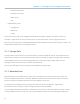
2.3. Planning Network can be accessed via a web browser. The management node must have the port 8888 open by default to allow access to the admin panel from the public network and to the cluster node from the internal network. The figure below shows a sample network configuration for a storage and management node. • A node that runs one or more storage access point services must have a network interface for the internal network traffic and a network interface for the public network traffic.
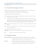
Chapter 2. Planning Acronis Storage Infrastructure The next figure shows a sample network configuration for a node with an S3 storage access point. S3 access points use ports 443 (HTTPS) and 80 (HTTP) to listen for incoming connections from the public network.
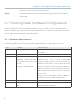
2.3. Planning Network In the scenario pictured above, the internal network is used for both the storage and S3 cluster traffic. The next figure shows a sample network configuration for a node with an Acronis Backup Gateway storage access point. Acronis Backup Gateway access points use port 44445 for incoming connections from both internal and public networks and ports 443 and 8443 for outgoing connections to the public network.
Chapter 2. Planning Acronis Storage Infrastructure 2.3.4 Network Recommendations for Clients The following table lists the maximum network performance a client can get with the specified network interface. The recommendation for clients is to use 10Gbps network hardware between any two cluster nodes and minimize network latencies, especially if SSD disks are used. Storage network interface Node max. VM max. I/O (replication) VM max.
2.4. Understanding Data Redundancy 2.3.5 Sample Network Configuration The figure below shows an overview of a sample Acronis Storage network. In this network configuration: • The Acronis Storage internal network is a network that interconnects all servers in the cluster. It can be used for the management, storage, and S3 internal services. Each of these services can be moved to a separate dedicated internal network to ensure high performance under heavy workloads.
Chapter 2. Planning Acronis Storage Infrastructure that will be maintained in the cluster. In general, replication offers better performance while erasure coding leaves more storage space available for data (see table). Acronis Storage supports a number of modes for each redundancy method. The following table illustrates data overhead of various redundancy modes. The first three lines are replication and the rest are erasure coding. Redundancy Min.
2.4. Understanding Data Redundancy All redundancy modes allow write operations when one storage node is inaccessible. If two storage nodes are inaccessible, write operations may be frozen until the cluster heals itself. 2.4.1 Redundancy by Replication With replication, Acronis Storage breaks the incoming data stream into 256MB chunks. Each chunk is replicated and replicas are stored on different storage nodes, so that each node has only one replica of a given chunk.
Chapter 2. Planning Acronis Storage Infrastructure • Network performance. All replicas are transferred between storage nodes over network. For example, 1 Gbps throughput can be a bottleneck (see Per-Node Network Requirements on page 20). • Distribution of data in the cluster. Some storage nodes may have much more data to replicate than other and may become overloaded during replication. • I/O activity in the cluster during replication. 2.4.
2.5. Understanding Failure Domains Data stream Fragment M chunks 1 2 3 4 5 N parity chunks 6 7 M + N chunks Storage nodes 2.4.3 No Redundancy Warning: Danger of data loss! Without redundancy, singular chunks are stored on storage nodes, one per node. If the node fails, the data may be lost. Having no redundancy is highly not recommended no matter the scenario, unless you only want to evaluate Acronis Storage on a single server. 2.
Chapter 2. Planning Acronis Storage Infrastructure outage or network disconnect), all CS services on it become unavailable at once. To protect against data loss under this policy, Acronis Storage never places more than one data replica per host. This policy is highly recommended for clusters of five nodes and more. • Disk, the smallest possible failure domain. Under this policy, Acronis Storage never places more than one data replica per disk or CS.
2.7. Understanding Cluster Rebuilding 2.7 Understanding Cluster Rebuilding The storage cluster is self-healing. If a node or disk fails, a cluster will automatically try to restore the lost data, i.e. rebuild itself. The rebuild process involves the following steps. Every CS sends a heartbeat message to an MDS every 5 seconds. If a heartbeat is not sent, the CS is considered inactive and the MDS informs all cluster components that they stop requesting operations on its data.
Chapter 2. Planning Acronis Storage Infrastructure least 2 TB free in case the largest node fails (while the largest node should have 1 TB free). Two recommendations that help smooth out rebuilding overhead: • To simplify rebuilding, keep uniform disk counts and capacity sizes on all nodes. • Rebuilding places additional load on the network and increases the latency of read and write operations. The more network bandwidth the cluster has, the faster rebuilding will be completed and bandwidth freed up.
CHAPTER 3 Installing Acronis Storage After planning out the infrastructure, proceed to install Acronis Storage on each server included in the plan. Acronis Storage is installed in a similar way on all required servers. One exception is the first server where you must also install the management panel (only one is allowed per cluster). Note: On all nodes in the same cluster, time needs to be synchronized via NTP. Make sure the nodes can access the NTP server. 3.
Chapter 3. Installing Acronis Storage Make a bootable USB drive by transferring the distribution image to it with dd. Important: Be careful to specify the correct drive to transfer the image to. For example, on Linux: # dd if=storage-image.iso of=/dev/sdb And on Windows (with dd for Windows): C:\>dd if=storage-image.iso of=\\?\Device\Harddisk1\Partition0 3.2 Starting Installation To start the installation, do the following: 1. Configure the server to boot from a DVD or USB drive. 2.
3.4. Configuring Network network settings, you can do so on the NETWORK & HOST NAME screen. If manual configuration is required, specify the necessary parameters for at least one network card and provide a hostname: either a fully qualified domain name (hostname, domainname) or a short name (hostname). 3.4.1 Creating Bonded Connections Bonded connections offer increased throughput beyond the capabilities of a single network card as well as improved redundancy.
Chapter 3. Installing Acronis Storage 3. In the Choose a Connection Type window, select Ethernet from the in the drop-down list, and click Create.
3.4. Configuring Network 4. In the Editing bond slave... window, select a network interface to bond from the Device drop-down list. 5. Configure other parameters if required. 6. Click Save. 7. Repeat steps 3 to 7 for each network interface you need to add to the bonded connection. 8. Configure other parameters if required.
Chapter 3. Installing Acronis Storage 9. Click Save. The connection will appear in the list on the NETWORK & HOSTNAME screen. 3.5 Choosing Components to Install To install Acronis Storage on a server, you need to choose a component to install on the Acronis Storage screen: The following options are available: • Management Panel. Install the web-based user interface for managing Acronis Storage clusters. • Storage. Turn the server into a node ready to run Acronis Storage services related to data storage.
3.5. Choosing Components to Install to the management panel. 3. In the Management network drop-down list, select a network interface and specify a port for internal management and configuration purposes (the port 8888 is used by default). 4. Create a password for the admin account of the management panel and confirm it in the corresponding fields. 5. Click Done. After completing the steps above, proceed to Selecting Destination Partition on page 42. 3.5.
Chapter 3. Installing Acronis Storage For security reasons, you will need to provide a token that can only be obtained from the management panel you have installed on the first server. A single token can be used to install the storage component on multiple servers in parallel. To obtain a token: 1. Log in to the Acronis Storage management panel.
3.5. Choosing Components to Install Click ADD NODE and a screen similar to open a screen similar to the welcome one. On it, a token will be shown (you can generate a new one if needed; generating a new token invalidates the old one). Having obtained the token, do the following on the Acronis Storage screen: 1. Choose Storage.
Chapter 3. Installing Acronis Storage 2. In the Management node field, specify the IP address of the node with the management panel. 3. In the Token field, specify the acquired token. 4. Click Done and proceed to Selecting Destination Partition on page 42. 3.6 Selecting Destination Partition You need to choose on which server disk the operating system will be installed. This disk will have the system supplementary role and will not be used for data storage.
3.7. Finishing Installation Having configured everything necessary on the INSTALLATION SUMMARY screen, click Begin Installation. Once the installation is complete, the server will automatically reboot. Your next steps depend on which server you installed Acronis Storage: • If you installed the management component on the first server (with or without the storage component), proceed to install the storage component on the second and other servers.