Data Collection Terminal 0 -10-0 M 04 A 8:20 QZ.
FCC Warning: Note: This equipment has been tested and found to comply with the limits for a Class A digital device, pursuant to Part 15 of the FCC rules. These limits are designed to provide reasonable protection against harmful interference when the equipment is operated in a commercial environment. The equipment generates, uses, and can radiate radio frequency energy.
Table of Contents 1. Introduction ................................................................. 4 Basic hardware and variations ................................................ 4 General specifications ............................................................. 5 2. Setup ............................................................................ 6 Site requirements .................................................................... 6 Unpacking and inspection ........................................
1. Introduction Basic hardware and variations The electronic hardware is a new, versatile platform designed for use with various applications. This manual describes, in detail, the electronic hardware aspects of the terminal you have purchased. The details concerning terminal firmware and host software are addressed in the manual which comes with the software.
General specifications A. Enclosure: 8.7 in. (23 cm) wide x 6.1 in. (16 cm) tall x 2.3 in. (6 cm) deep. Clamshell construction of 0.125 in. (3 mm) thick Polycarbonate/ABS injection molded flame retardant plastic. Includes reversible mounting bracket and access door which protects I/O ports. B. Multilayer main logic board with internal ground and power planes. C. Z-180 Microprocessor. D. Up to 512 Kbyte configurable memory. Most common configuration is 64K ROM and 128K RAM. E. Lithium battery backed RAM.
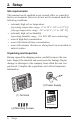
2. Setup Site requirements The terminal can be installed in any normal office or controlled factory environment.
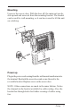
Mounting Unscrew the access door. With the door off, the main unit can be slid upward and removed from the mounting bracket. The bracket can be used for wall mounting, or it can be reversed to tilt the unit on a desktop. Power up Plug in the power cord coming from the wall mount transformer into the terminal. Reattach the access door and secure the unit to the reversible bracket. Replace screw on the access door. NOTE: Other connections are made in the same fashion.
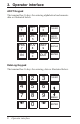
3. Operator interface ADCT Keypad The terminal has 16 keys for entering alphabetical and numeric data as illustrated below. QZ. 1 ABC 2 DEF 3 CLEAR GHI 4 JKL 5 MNO 6 BACK SPACE PRS 7 TUV 8 WXY 9 ALPHA IN -SP 0 OUT ENTER DataLog Keypad The terminal has 16 keys for entering data as illustrated below.
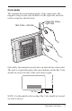
Card reader The terminal has an internal magnetic stripe card reader. The magnetic stripe on the card should be on the right side when the card is swiped as shown below. Bar Code - left side Magnetic stripe right side 0.25" Nominal Optionally, the terminal can also have an internal bar code reader. The card is swiped through in the same fashion, but the Bar Code should be on the left side of the card when swiped. 1.00" Min.
4.
(For RS485 terminals only) Select option 1 for RS485 Select the baud rate 0 for 1200, 1 for 2400, 2 for 4800, 3 for 9600 and 4 for 19,200 baud. (For Ethernet terminals with ATR9800 only) Select option 2 for Ethernet Select the baud rate option 3 for 9600 baud (Leave this as the default for Ethernet.) Select the TCPIP address (Your network administrator will have this information.
Select TRANSACTION TIME OUT (This controls how long the terminal will restrict between badge swipes. Example: You want to keep your employees off the terminal for at least 30 minutes for lunch, then set Transaction Time Out to 30.) Select TERMINAL ID (default is 1, select the ID for terminal, each terminal MUST have a unique ID) The terminal MUST be powered down and back up to accept the new TCPIP information.
Ethernet port The Ethernet port is located on the lower left corner of the terminal. It is a 10 position 8-pin female port which will accept a male 10BASE-T (RJ-45) modular connector. The terminal has the capability to communicate across an intranet, a WAN or the Internet. Note: Ethernet communicates via TCPIP 10BASE-T only.
RS-232 Serial port The RS-232 serial port is located on the lower left corner of the terminal. It is a 6 position 4-pin female port which will accept a male RJ-11 modular connector. ND WA RS 485 The Acroprint Data Collection Terminal can use RS-232 serial communication to connect directly to a host computer. A connection for an IBM PC or compatible is shown below. RS 232 9V Cabling to Host Computer with DB-25 Port (Use DB-25 RS-232 Host Cable Assembly. See page 26.
RS-232 Serial printer cables The terminal serial port is used for connection to a serial printer. Printers, such as the serial printer shown on page 24, use a circular DIN connection. The Serial DIN Cable is shown below (see page 26). Cabling to serial printer with 6-pin DIN port DIN connector 72-0158-002 Serial DIN Cable Schematic NOTE: Schematic connections are shown from END VIEW. (As viewed from the outside of the connectors.
Local Area Network: RS-485 serial port The RS-485 serial port is located on the lower left corner of the terminal. It is a 6 position 4-pin female port which will accept a male RJ-11 modular connector. ND WA RS 485 RS 232 9V The terminal can use RS-485 2-wire serial communication, allowing up to 32 terminals to be connected to one host port. An RS-232 port on the host is typically used in conjunction with an RS-232/RS-485 converter to complete the connection.
RS-485 Serial cables Junction Box Daisy Chain Wiring Diagram 4 5 + + + 3 + 4 2 5 + + + 3 + 4 2 5 Junction Box To another Junction Box + + + 3 + 2 Junction Box Teflon Cable Junction Box To terminal (short as possible) "Standard" Modular Cable "Reversed" Modular Cable Schematic Schematic DB-25 to RJ-11 Adaptor (Adaptor C) Schematic NOTE: Connectors are shown from END VIEW. (As viewed from the outside of the connectors.
Modem port Terminals which are equipped with a MODEM port, will not have an RS-485 port. The MODEM port, when installed, physically replaces the RS-485 port and occupies the same location - the lower left corner of the badge terminal. It is a 6 position 4-pin female port which will accept a male RJ-11 modular connector. ND WA RS 4MO8D5EM RS 232 9V The internal modem (modulator/demodulator) converts electronic data into tones which are then transmitted over phone lines.
Modem cables The cabling for modem operation is typically very simple. The modular connection uses the two inner wires of the RJ-11 jack for tip and ring. Connect one end of the cable to the terminal and plug the other end into your RJ-11 type modular telephone wall jack. If a modular wall jack is not available, obtain an adaptor from your local telephone company.
Wand port The Wand port is located on the lower left corner of the terminal. It is a 6-pin DIN port which will accept a circular DIN connector. ND WA RS 485 RS 232 9V The Wand, when connected, uses only 3 of the 6 pins available on the DIN connection. If a Bar Code Gun (non-contact reader) is used, the center pin supplies additional power. The terminal uses 2 of the remaining pins as logic lines for external controls.
Wand and Y-Cable Disconnect power to the terminal before connecting the Bar Code Wand. The wand is capable of reading bar code stripes by passing it directly over the label. Check the software manual to identify the codes your terminal will read. Bar Code Wand The Y-cable shown below allows for connection of both a wand and other external devices. The single end of the cable is plugged into the terminal. A wand can be connected to one split and another device to the other.
Parallel port The parallel port is located on the right side of the Acroprint Data Collection Terminal. It is a 25 pin female port which will accept a 25pin male connector. This type of parallel port is typically used on IBM® PC or IBM-PC compatible computers. The Acroprint Data Collection Terminal provides strain relief if the connector is locked in by the securing screws. Additional strain relief can be obtained by securing the parallel cable to the wall or mounting surface.
Parallel cable The parallel port is typically used for connection to a parallel printer. Shown below is a parallel interface cable. Since this is the same cable that is used to connect an IBM-PC or compatible to a printer, it will likely be available from most computer dealers offthe-shelf. One end is a male DB-25 connector, the other end is a 36-pin Centronics-type connector to match the parallel port on the printer. Parallel Cable Schematic Note: Schematic connections are shown from END VIEW.
5.
Power Supplies Description/Illustration Part Number Lighter Power 12 VDC Adaptor 72-0160-000 120VAC to 9VAC Power Supply 56-0113-000 230VAC to 9VAC Power Supply European 56-0116-000 240VAC to 9VAC Power Supply British 56-0117-000 230VAC to 9VAC Power Supply Parallel Blades 56-0118-000 External Relay Box, External Buzzer External Relay Box External Buzzer 120 V 240 V 01-0121-000 01-0121-002 01-0122-000 Companion products 25
Cables Description/Illustration Part Number Standard Modular Cable length - 7 feet - 50 feet 72-0146-000 72-0146-004 Reverse Modular Cable length - 7 feet - 50 feet 72-0164-000 72-0164-004 Serial DIN Cable - (RS-232/printer) 72-0158-002 use with 40/80 column printer Y-Cable (splitter) 72-0159-000 DB-25 RS-232 Host Cable Assembly Includes DB-25 (RS-232/host) to RJ-11 female adaptor and Standard Modular Cable.
Cables, Converter, Badge Racks Description/Illustration Part Number DB-9 RS-232 Host Cable Assembly Includes DB-9 (RS-232/host) to RJ-11 female adaptor and Standard Modular Cable. length - 7 feet - 50 feet 25-0116-004 25-0116-008 Modem Adapter Cable Assembly Includes DB-25 (modem) to RJ-11 male adaptor and Standard Modular Cable.
5640 Departure Drive Raleigh, NC 27616 919.872.5800 www.acroprint.com P/N 06-0262-000 Rev.