
Owner manual


HandPunch 3000/4000 Manual
31
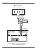
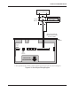
Wiring Connections
Once the HandPunch is attached to the wall plate the wiring connections to
the HandPunch can be made (see Figure 4-1).
WALL
Serial RS-232
Optional Modem
or Ethernet
Wall Plate
Top of
Terminal
Top of HandPunch
Power
Connectors
J7 Battery
Jumper
Terminal
Strips
Reset
Switch
RJ-11
RS-422
Figure 4-1: Wiring Connections
The following tables provide the pinouts for the terminal strips on the
HandPunch.
• “Table2”onpage32providesthepinoutsforTS-2:InputConnections.
• “Table3”onpage32providesthepinoutsforTS-3:CardReaderandOutput
Connections.
• “Table4”onpage33providesthepinoutsfortheSerialRS-232Connection.
• “Table5”onpage33providesthepinoutsfortheRS-422HandPunchto
HandPunch Network Connection.
The following figures provide the pinout diagrams for the RJ-11 and RS-232
connectors:
• “Figure4-2”onpage33providesthepinoutsforJ3,theRJ-11/RS-422
Network Configuration.
• “Figure4-3”onpage34providesthepinoutsforJ8,theRS-232SerialPrinter
Connection.
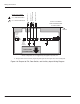
Wiring
Examples