
Owner manual


HandPunch 3000/4000 Manual
35
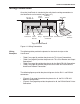
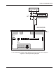
Figure 4-5: Lock Output Wiring Diagram
* These components are not supplied by Recognition Systems, Inc.
TOP OF THE
HANDREADER
HINGE
WALL TO WHICH
THE HANDREADER
IS ATTACHED
+
-
* POWER SUPPLY
+12 to 24 VDC Max
NC
NO
*LOCK
RELAY
*ELECTRIC LOCK
OR STRIKE
+
-
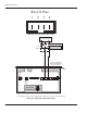
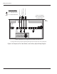
** The operation of the Auxiliary Outputs depend upon how the inputs have been configured.
12 to 24 V
AC/DC
Input
14 13
12
11
10
9
8 7 6 5 4
3 2
1
1 2
RJ-11
RS-422
Connection