
Owner manual


Appendix C - Old Board Configuration
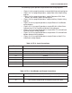
86
26 25 24 23 22
21 20 19 18
17
16
15 14 13 12 11 10
9 8
7
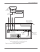
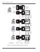
These components are not supplied by Recognition Systems, Inc.
The Aux 1 and Aux 2 input contact states are programmable within
the HandPunch unit.
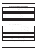
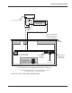
TOP OF THE
HAND READER
HINGE
WALL TO WHICH
THE HANDPUNCH
IS ATTACHED
AUX OUTPUT 2
AUX OUTPUT 1
AUX INPUT 2
AUX INPUT 1
N.C. DOOR SWITCH
REQUEST TO EXIT
SWITCH LEGEND
N.C. DOOR SWITCH
N.O. MOMENTARY
GROUND
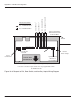
CLOCK
CLOCK
GROUND
DATA
DATA
+5 VDC POWER
(SEE NOTE BELOW)
NOTE: For +12 VDC magnetic stripe readers, connect the magnetic stripe reader
power supply to J6 on the Hand Punch.
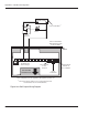
Access Control
Panel
ABA-Track II
Magnetic Stripe Card Reader
HandPunch
Power
Connection
RJ-11/RS-422
4-wire
Network
Optional RJ-45
Ethernet or
RJ-11 Modem
RJ-45/RS-232
Printer Output
J6
+12 VDC for
12 Volt External
Card Readers
1
2
1
2
2
1
Figure 13-10: External Card Reader Wiring DIagram