AIV-HM76V1FL Series User Manual AIV-HM76V1FL Series An in-vehicle computer designed for comprehensive mobile applications 3rd Generation Intel Core i7, i3, or Celeron Processor with Intel PCH HM76 Chipset User Manual Acrosser Technology Co., Ltd. www.acrosser.
AIV-HM76V1FL Series User Manual Disclaimer For the purpose of improving reliability, design and function, the information in this document is subject to change without prior notice and does not represent a commitment on the part of Acrosser Technology Co., Ltd. In no event will Acrosser Technology Co., Ltd. be liable for direct, indirect, special, incidental, or consequential damages arising out of the use or inability to use the product or documentation, even if advised of the possibility of such damages.
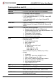
AIV-HM76V1FL Series User Manual Table of Contents 1. System Introduction....................................................................... 5 1.1. Specifications.............................................................................................................. 5 1.2. Packing List................................................................................................................. 8 1.3. Features.......................................................................................
AIV-HM76V1FL Series User Manual 4.4. Application Installation Page..................................................................................... 43 4.5. Document Page......................................................................................................... 46 5. Software Installation and Programming Guide......................... 47 5.1. Introduction................................................................................................................ 47 5.1.1. CAN Bus.......
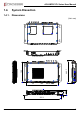
AIV-HM76V1FL Series User Manual 1. System Introduction The AIV-HM76V1FL Series is a fanless In-Vehicle Computer designed to perform multiple in-car applications. These designs include smart power management, high efficient thermal module, and diversity of integrated communication technology such as CAN bus, WiFi, 3.5G wireless WAN, Bluetooth, and GPS. 1.1. Specifications System CPU • AIV-HM76V1FLCi7: Intel Core i7-3517UE Processor (4M Cache, 1.
AIV-HM76V1FL Series User Manual Communication and I/O 6 Ethernet Chip • Intel 82574L PCIe LAN Ethernet • 2 x PCIE*1 Intel GbE chip via RJ-45 connector USB Port • 3 x External USB3.0 connectors • 2 x Mini PCIe slot for 3.5G WiFi module • 1 x for proprietary Bluetooth -> (1 x 5-pin 1.0mm WTB Connector 180°) • 1 x for proprietary GPS -> (1 x 5-pin 1.
AIV-HM76V1FL Series User Manual Other Features Audio • Realtek audio codec ALC662 CMOS • RTC (+/- 2 seconds for 24 hours) • Lithium battery (3V) for CMOS data backup Hardware Monitoring • • • • RTC battery voltage CPU and system temperature CPU voltage Voltage (12V, 5V, 3.3V) Antenna Antenna Type • 5 x SMA (1x for GPS, 1x for Bluetooth, 1x for 3.
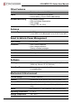
AIV-HM76V1FL Series User Manual Storage Humidity • 0 ~ 60% Certification • CE / FCC class B / E Mark 13 Optional Modules 1.2. GPS • WIESON ZYM-5020,RF Cable Bluetooth • 2.1 Qcom QBTM400-01, RF Cable 3.5G • Sierra MC8705, RF cable (use mini PCIe 1) WiFi • Intel Centrino 6205ANHMW WiFi module 802.11 a/b/g/n, RF Cable (use mini PCIe 2) Packing List Check if the following items are included in the package.
AIV-HM76V1FL Series User Manual 1.4. System Dissection 1.4.1. Dimensions 190 205.7 (Unit: mm) 337.2 www.acrosser.com 49.
AIV-HM76V1FL Series User Manual 1.4.2. I/O Panel Front IO Power Input COM COMBO Remote HDMI USB3.0 LAN Rear I/O WiFi 3G GPS Bluetooth Fuse GPIO 10 Acrosser Technology Co., Ltd.
AIV-HM76V1FL Series User Manual Status/HDD/Power LED Display LED Light Display G Green Status G Green HDD Y Yellow Power LED Status LED Flashing Status: A Status LED is used to indicate the status of the system. In normal condition, the LED will flash a number of blink to state the status. Each blink remains 200 ms ON followed by a 200 ms OFF. Each Cycle will have a 2-second OFF in between. LED Flashing Numbers Status 0 (Constant On) Power output runs normally.
AIV-HM76V1FL Series User Manual HDMI1, HDMI2 Pin # Signal Pin # Signal 1 DATA2+ 2 GND 3 DATA2- 4 DATA1+ 5 GND 6 DATA1- 7 DATA0+ 8 GND 9 DATA0- 10 CLK+ 11 GND 12 CLK- 13 NC 14 NC 15 DDCCL 16 DDCDA 17 GND 18 +5V 19 HPD USB1, USB2, USB3 Pin # Signal Pin # Signal 1 5V 5 SS_RX - 2 Data - 6 SS_RX + 3 Data + 7 GND 4 GND 8 SS_TX - 9 SS_TX + LAN1, LAN2 LED LED1 LED2 12 Light Status Off 10Mbps Green 100Mbps Orange 1000Mbps Yellow Link/Active
AIV-HM76V1FL Series User Manual COMBO COMBO Connector Pin # Signal Pin # Signal 1 USB+ 11 DDCCL 2 USB- 12 VCC12 3 GND 13 GND 4 VCC5 14 Audio_R 5 GND 15 GND 6 Red 16 MIC_B 7 Green 17 Audio_L 8 Blue 18 MIC_T 9 HSYNC 19 NC 10 VSYNC 20 DDCDA COMBO Cable USB2.0 A-Type Female D-SUB 40215 Female SCSI 20pin Male Ground DC Power 2.5 Male Positive Audio-L 3.5 Stereo Audio-R Female Ground www.acrosser.
AIV-HM76V1FL Series User Manual COM1, COM2, COM3, COM4 COM1~3 Pin # COM4 Signal Pin # Signal 1 DCD 1 TX4+ 2 SIN 2 TX4- 3 SOUT 3 NC 4 DTR 4 NC 5 GND 5 GND 6 DSR 6 NC 7 RTS 7 NC 8 CTS 8 RX4- 9 RI 9 RX4+ GPIO Pin # Definition Wire Color 1 GPO0 Brown 2 GPO1 Orange 3 GPO2 Green 4 GPO3 Blue 5 GND Black 6 GND Glay 7 CAN_H Red/White 8 CAN_L White 9 GND Red 10 i-Button Purple 11 GPI4 Light Green 12 GPI5 Light Blue 13 GPI6 Pink 14 GPI7
AIV-HM76V1FL Series User Manual 1.4.3.
AIV-HM76V1FL Series User Manual 1.4.4. Power Board Top View LED1 CN_12V1 CN_12V2 16 Acrosser Technology Co., Ltd.
AIV-HM76V1FL Series User Manual 2. Components Assembly 2.1. 2.5” SATA SSD Installation Step 1: Loosen the two disk-tray screws by fingers. Step 2: Pull out the disk-tray and install your 2.5” SATA disk. Step 3: Fasten the disk with 4 screws provided in the package. Step 4: Firmly push the disk-tray back into the disk compartment. The disk is now connected with the system. Step 5: Push in the disk-tray and fasten the two disk-tray screws by your screw driver or fingers. Step 6: www.acrosser.
AIV-HM76V1FL Series User Manual 2.2. 18 CF Card Installation Step 1: Loosen the two card-tray screws by your screw driver. Step 2: Pull out the card-tray. Loosen the two screws that locks the card holder. Slide your CF card into the card holder. Screw back the card holder. Step 3: If there is no need to install the SIM card, push in the card-tray and fasten the two card-tray screws by your screw driver. Step 4: Complete. Acrosser Technology Co., Ltd.
AIV-HM76V1FL Series User Manual 2.3. SIM Card Installation Before completing the CF card installtion, you may want to install the SIM card accroding to your system configuration. Note: Step 1: Leave the CF card-tray on table. Step 2: Use a clip to install your SIM card into the SIM1 slot on the mainboard. Pay attention to its orientation, and do not scratch the contacts. Step 3: Push in the card-tray and fasten the two card-tray screws by your screw driver. Step 4: Complete.
AIV-HM76V1FL Series User Manual 2.4. 20 DIMM Card Installation Step 1: Use your screw driver to remove the DIMM card cover plate located at the chassis bottom. Step 2: Install your DIMM card into the CN_DIMM1 or CN_DIMM2 slot on the mainboard. Pay attention to its orientation, and do not scratch the contacts. Step 3: Place back the DIMM card cover plate and have it fastened. Step 4: Complete. Acrosser Technology Co., Ltd.
AIV-HM76V1FL Series User Manual 2.5. 3.5G / WiFi Module Installation MINIPCIE2 (WiFi) MINIPCIE1 (3.5G) Step 1: Use your screw driver to remove the cover plate located at the chassis bottom. Step 2: For 3.5G module, install to the MINIPCIE1 slot on the mainboard. For WiFi module, install to the MINIPCIE2 slot on the mainboard. Pay attention to its orientation, and do not scratch the contacts. Step 3: Attch the RF plug from the system to your module.
AIV-HM76V1FL Series User Manual 2.6. Antenna Connection Connect your antenna needed according to your system configuration. 2.7. Power Connection Connect your power cable. 9V ~ 32V DC input connector Terminal Block: 3 pin Pitch: 5.08mm 22 Pin # Signal V+ 9V ~ 32V DC Power Input IGN Ignition On (Hi Active) V- GND Acrosser Technology Co., Ltd.
AIV-HM76V1FL Series User Manual 2.8. Blade-type Fuse Holder Power-input fuse suggestion: Output: 12V/100W (Input: 9V~32V/111W, Efficiency: 90%) Note: Car Battery Blade-type fuse suggestion Remarks 12V System CONQUER ATQ-10 Voltage Rating: 32V; Current Rating: 10A 24V System CONQUER ATQ-5 Voltage Rating: 32V; Current Rating: 5A You may have to use a needle-nose pliers to grip on the fuse and pull it out. www.acrosser.
AIV-HM76V1FL Series User Manual 3. BIOS Settings This chapter describes the BIOS menu displays and explains how to perform common tasks needed to get the system up and running. It also gives detailed explanation of the elements found in each of the BIOS menus. The following topics are covered: • Main Setup • Advanced Setup • Chipset Setup • Boot Setup • Security Setup • Save & Exit Setup Once you enter the Award BIOS™ CMOS Setup Utility, the Main Menu will appear on the screen.
AIV-HM76V1FL Series User Manual Main Aptio Setup Utility - Copyright (C) 2012 American Megatrends, Inc. Advanced Chipset Boot Security Save & Exit Processor Information Intel(R) Celeron(R) CPU 1047UE @ 1.40GHz IvyBridge Name 1400 MHz Frequency Processor ID 306a9 E1 Stepping 2Core(s) / 2Thread(s) Number of Processors 19 Microcode Revision GT2 (900 MHz) GT Info IGFX VBIOS Version Memory RC Version Total Memory Memory Frequency 2143 1.5.0.0 4096 MB (DDR3) 1600 MHz ME FW Version ME Firmware SKU 8.0.10.
AIV-HM76V1FL Series User Manual 3.2. Advanced Setup Main Aptio Setup Utility - Copyright (C) 2012 American Megatrends, Inc. Advanced Chipset Boot Security Save & Exit SATA Configuration USB Device F81216 Second Super IO Configuration W83627DHG HW Monitor Power Sub System SATA Device Options Settings →←: Select Screen ↑↓: Select Item Enter: Select +/-: Change Opt. F1: General Help F2: Previous Values F3: Optimized Defaults F4: Save & Exit ESC: Exit Version 2.15.1226.
AIV-HM76V1FL Series User Manual • • 3.2.2. SATA Controller(s) Options Enabled / Disabled Description Enable or disable SATA device. SATA Mode Selection Options IDE / AHCI Description Determines how SATA controller(s) operate. USB Device USB configuration parameters. Aptio Setup Utility - Copyright (C) 2012 American Megatrends, Inc. Advanced USB Device USB Devices: 1 Keyboard, 1 Mouse, 2 Hubs Legacy USB Support [Enabled] Enable Legacy USB support.
AIV-HM76V1FL Series User Manual 3.2.3. F81216 Second Super IO Configuration System second super IO chip parameters. Aptio Setup Utility - Copyright (C) 2012 American Megatrends, Inc. Advanced F81216 Second Super IO Configuration F81216 Second Super IO Chip COM 1 Configuration COM 2 Configuration COM 3 Configuration COM 4 Configuration F81216 SecondIO COM4 422/485 function [RS-422] Set Parameters of COM 1 →←: Select Screen ↑↓: Select Item Enter: Select +/-: Change Opt.
AIV-HM76V1FL Series User Manual 3.2.4. W83627DHG HW Monitor Monitor hardware status. Aptio Setup Utility - Copyright (C) 2012 American Megatrends, Inc. Advanced F8121PC Health Status SYSTIN temperature CPUTIN temperature VCORE 5V 12V 3.3V VBAT : : : : : : : +41°C +51°C +0.840 V +5.150 V +11.880 V +3.440 V +3.280 V →←: Select Screen ↑↓: Select Item Enter: Select +/-: Change Opt. F1: General Help F2: Previous Values F3: Optimized Defaults F4: Save & Exit ESC: Exit Version 2.15.1226.
AIV-HM76V1FL Series User Manual 3.2.5. Power Sub System Power Sub System. Aptio Setup Utility - Copyright (C) 2012 American Megatrends, Inc. Advanced Model Firmware Version HM76V1 V1.0 Power Board Type [In-Vehicle] Battery Voltage 11.62 V Battery Low Monitor Battery Low Delta Remote Switch Power On Delay (Sec.) Soft-Off Delay (Sec.) Shutdown Delay (Sec.) Hard-Off Delay (Sec.) [Disabled] [1.
AIV-HM76V1FL Series User Manual • • • • 3.3. Power On Delay (Sec.) Options 2 ~ 60 Description The delay between power on and system work. Soft-Off Delay (Sec.) Options 0 ~ 3600 Description The delay before system shutdown. Shutdown Delay (Sec.) Options 120 ~ 3600 Description The delay between system shutdown and system off. Hard-Off Delay (Sec.) Options 0 ~ 3600 Description The delay before all power off. Chipset Setup Main Aptio Setup Utility - Copyright (C) 2012 American Megatrends, Inc.
AIV-HM76V1FL Series User Manual • LAN 1 ASPM, LAN 2 ASPM Options Description L0s, L1, L0sL1, Auto, Disabled Sets the ASPM (Active State Power Management Settings) level for LAN1 and LAN2. • Audio Control detection of the Azalia device. Options Disabled Auto 3.3.1. Description Azalia will be unconditionally disabled. Azalia will be enabled if present, disabled otherwise. SB USB Configuration Aptio Setup Utility - Copyright (C) 2012 American Megatrends, Inc.
AIV-HM76V1FL Series User Manual 3.3.2. Graphics Configuration Aptio Setup Utility - Copyright (C) 2012 American Megatrends, Inc. Chipset System Agent Bridege Name System Agent RC Version VT-d Capability IvyBridge 1.5.0.0 Unsupported DVMT Pre-Allocated DVMT Total Gfx Mem [64M] [256M] Primary IGFX Boot Display [VBIOS Default] Select DVMT 5.0 Pre-Allocated (Fixed) Graphics Memory size used by the Internal Graphics Device. →←: Select Screen ↑↓: Select Item Enter: Select +/-: Change Opt.
AIV-HM76V1FL Series User Manual 3.4. Boot Setup Main Aptio Setup Utility - Copyright (C) 2012 American Megatrends, Inc. Advanced Chipset Boot Security Save & Exit Boot Configuration Setup Prompt Timeout Bootup Numlock State 2 [On] Boot Logo [Enabled] CSM16 Module Version 07.69 Number of seconds to wait for setup activation key. 65535(0xFFFF) means indefinite waiting. Driver Option Priorities Boot Option Priorities →←: Select Screen ↑↓: Select Item Enter: Select +/-: Change Opt.
AIV-HM76V1FL Series User Manual 3.5. Security Setup Main Aptio Setup Utility - Copyright (C) 2012 American Megatrends, Inc. Advanced Chipset Boot Security Save & Exit Password Description If ONLY the Administrator’s password is set, then this only limits access to Setup and is only asked for when entering Setup. If ONLY the User’s password is set, then this is a power on password and must be entered to boot or enter Setup. In Setup the User will have Administrator rights.
AIV-HM76V1FL Series User Manual 3.6. Save & Exit Setup Main Aptio Setup Utility - Copyright (C) 2012 American Megatrends, Inc. Advanced Chipset Boot Security Save & Exit Save Changes and Exit Discard Changes and Exit Exit system setup after saving the changes. Save Options Save Changes Discard Changes Restore Defaults Save as User Defaults Restore User Defaults Boot Override →←: Select Screen ↑↓: Select Item Enter: Select +/-: Change Opt.
AIV-HM76V1FL Series User Manual 4. Driver and Utility Installation 4.1. Driver CD Interface Introduction Acrosser provides a Driver CD compiled with all the drivers, utilities, applications and documents this product may need. Put the Driver CD into your CD-ROM drive. The Driver CD will automatically detect the mainboard information to see if they are matched. The following error messages appear if you use an incorrect Driver CD version with your mainboard. Please find the correct Driver CD to proceed.
AIV-HM76V1FL Series User Manual Put the correct Driver CD of your mainboard into your CD-ROM drive. The following installation screen should appear. If not, enter the root folder of the Driver CD, run the excution file “Setup.exe“. 38 Acrosser Technology Co., Ltd.
AIV-HM76V1FL Series User Manual 4.2. Driver Installation Page Step 1: Select the “Driver” tab. Click the “Select All” button to select all the driver checkboxes, and then click “Install” button to start installing all the selected drivers. Step 2: The driver installation completeed. The configuration will be valid after reboot. www.acrosser.
AIV-HM76V1FL Series User Manual Note: Select the “Clear All“ button will clear all the selections, and then you can select the driver you want to install one by one, but the “Chipset” driver has to be installed before installing all the others. 4.3. Utility Installation Page Before launching the utility, you should install ”Driver” to initiate peripherals, e.g. GPIO and WatchDog. This “Test Utility” can be used to verify both system GPIO and WatchDog features.
AIV-HM76V1FL Series User Manual Step 2: The “Test Utility” screen appears. Select (1) GPIO Utility: Select (2) WatchDog Utility: www.acrosser.
AIV-HM76V1FL Series User Manual Select (3) Power Subsystem: Select (4) Can Bus: Select (5) I-Button: 42 Acrosser Technology Co., Ltd.
AIV-HM76V1FL Series User Manual 4.4. Application Installation Page Step 1: Select the “Application” tab. Click the “Acrobat Reader” box. Step 2: Please install “Acrobat Reader”. This application is needed for reading the User Manual in PDF format. www.acrosser.
AIV-HM76V1FL Series User Manual Step 3: Please install “Intel_MEI” and “Acrosser Driver” into the system. Windows OS will create “AcroDev” device. Step 4: If the “Windows Security” warning message appears, select “Install this driver software anyway” to go on next step. 44 Acrosser Technology Co., Ltd.
AIV-HM76V1FL Series User Manual Step 5: Install “Drivers for Optional Modules”. www.acrosser.
AIV-HM76V1FL Series User Manual 4.5. Document Page The user manual is stored in the “Document” folder. Note: 46 To read the PDF file, you will have to install “Acrobat Reader” first. Please refer to the “Application Installation Page”. Acrosser Technology Co., Ltd.
AIV-HM76V1FL Series User Manual 5. Software Installation and Programming Guide 5.1. Introduction 5.1.1. CAN Bus 5.1.1.1. Overview The CAN bus APIs provide interfaces to CAN bus subsystem. By invoking these APIs, programmers can implement the applications which have the functions listed below: 1. Set the BAUD rate. 2. Send the CAN packages over the CAN bus. 3. Receive the CAN packages via the CAN bus hardware interface. 4.
AIV-HM76V1FL Series User Manual To transmit a CAN packet, the programmer has to fill in the fields in the variable of type CanMsg and pass this CanMsg variable as an argument to invoke the APIs. The fields in CAN message are described below: id: This field holds the ID information of the CAN packet. In a ‘Standard Data Frame’ CAN packet, the ID field consists of 11 bits of binary digitals. In an ‘Extended Data Frame’ CAN packet, the ID field consists of 29 bits of binary digitals.
AIV-HM76V1FL Series User Manual msg.data[2] = 0xc3; msg.length = 3; 5.1.2. GPIO and Watchdog 5.1.2.1. Overview This model provides both a GPIO interface and a Watchdog timer. Users can use the GPIO and Watchdog APIs to configure and to access the GPIO interface and the Watchdog timer. The GPIO has four input pins and four output pins. The Watchdog timer can be set to 1~255 seconds. Setting the timer to zero disables the timer. The remaining seconds of the timer to reboot can be read from the timer. 5.1.
AIV-HM76V1FL Series User Manual The power subsystem connects to the main system via the COM port. On the Linux platform, the actual port number to which the Power Subsystem connects is determined by the Linux. The default supported COM interfaces on Linux are COM1~COM4. Users must take extra steps to configure Linux kernel in order to support COM ports which do not fall into the range COM1 ~ COM4. Please refer to Appendix A for more information.
AIV-HM76V1FL Series User Manual Syntax: i32 getCanBaudRate(u8 *baud) Description: This function gets the current setting of the Baud Rate of the CAN Bus. This function gets an ‘unsigned char’ to represent the Baud Rate.
AIV-HM76V1FL Series User Manual Syntax: i32 sendCanMessage(struct CanMsg *buffer, u8 count) Description: This function sends out CAN packages over the CAN bus. Parameters: If there is more than one CAN packet to send, these CAN packages are stored in an array of type ‘CanMsg’. This function sends out packets in a sequential fashion. The memory address of the first CAN packet to be sent is pointed at by the parameter ‘buffer’. The number of CAN packets to be sent is indicated by the parameter ‘count’.
AIV-HM76V1FL Series User Manual Syntax: i32 getCanMask(struct CanMask *mask) Description: This function gets the current setting of the acceptance masks. Masks are used to determine which bits in the ID field of the CAN packet are examined with the filters. There are two acceptance masks (mask0 and mask1) and six acceptance filters (filter0 ~ filter5) in the CAN Bus subsystem. Filter0 ~ filter1 are associated with mask0. Filter2 ~ filter4 are associated with mask1.
AIV-HM76V1FL Series User Manual Syntax: i32 setCanMask(struct CanMask mask) Description: This function sets the bit patterns to the indicated mask. The target mask is indicated by the ‘maskId’ field in a CanMask variable. Parameters: This functions takes a variable of type ‘CanMask’. User set the bit patterns they want to the ‘mask’ field in a ‘CanMask’ variable. struct CanMask { u8 maskId; // 0 or 1 u32 mask; } For example: struct CanMask varMask; i32 result; varMask.maskId = 1; varMask.
AIV-HM76V1FL Series User Manual Syntax: i32 setCanFilter(struct CanFilter *varFilter) Description: This function sets the bit pattern to the filter. By indicating the ‘filterType’ field in the ‘varFilter’ variable, the bit pattern in the ‘filter’ field will be taken as an ‘Standard ID’ filter or ‘Extended ID’ filter.
AIV-HM76V1FL Series User Manual 5.2.2. GPIO and Watchdog 5.2.2.1. GPIO Syntax: i32 getChLevel(u8 *val) Description: Get the status of GPIO input pins and output pins, and put the value at *val. Parameters: This function takes a pointer to an unsigned char variable as the parameter. The bit0 ~ bit3 in the pointed variable ‘*val’ is the status of the output pins. The bit4 ~ bit7 in the pointed variable ‘*val’ is the status of the input pins.
AIV-HM76V1FL Series User Manual 5.2.2.2. Watchdog 5.2.3. Syntax: u8 getWtdTimer(void) Description: This function read the value of the watchdog time counter and returns it to the caller. Parameters: None. Return Value: This function returns the value of the time counter and returns it to the caller as an unsigned character. Syntax: void setWtdTimer(u8 val) Description: This function sets the watchdog timer register to the value ‘val’ and starts to count down. The value could be 0 ~ 255.
AIV-HM76V1FL Series User Manual Syntax: i32 setPicDefault(void) Description: The function restores the Power Subsystem to the default values. After calling this API, the items listed below are restored to its default value: Remote Switch Default: Disabled Battery Monitor Default: Disabled Battery Voltage Delta Value Default: 1.
AIV-HM76V1FL Series User Manual Syntax: i32 setRemoteSwitch(u8 val) Description: The function sets the status of the Remote Switch. Parameters: This function takes an unsigned char as the parameter. The value of this parameter can be ‘ENABLED’ (0x5A) or ‘DISABLED’(0xA5). Return Value: If this function works successfully, it returns 0, any other value standards for error.
AIV-HM76V1FL Series User Manual 60 Syntax: i32 getBattDelta(float *val) Description: This function gets the delta value. The delta value is the maximum voltage deviation of the power from its nominal voltage. If the function of Battery Monitor is ON, the Power Subsystem shuts the system down when the voltage deviation of the power is larger than the delta value. Parameters: This function takes a pointer to a float variable as the parameter.
AIV-HM76V1FL Series User Manual Syntax: i32 getSoftOffDelay(u32 *Time) Description: The Soft Off Delay is the interval between that the system receives a power off signal and that the system generates a power off signal. This function gets the interval. Parameters: The parameter is a pointer which points to an unsigned long variable. The returned value is stored at this variable. The unit of the returned value is in seconds.
AIV-HM76V1FL Series User Manual 5.2.4. 62 Syntax: i32 getShutdownDelay(u32 *val) Description: This function gets the Shutdown delay. Parameters: This function takes a pointer to an unsigned long variable as the parameter. The delay time will be put at the memory which is pointed by the parameter ‘val’. Return Value: If this function works successfully, the function returns 0, any other value stands for error.
AIV-HM76V1FL Series User Manual 5.3. Appendix A Users have to modify the boot loader configuration to support COM port. Take the grub configuration file as an example. Add ‘8250.nr_uarts=XX noirqdebug’ at the setting of kernel. Here, XX represents the number of COM ports the system will support. Because the power subsystem connects to main system via COM port, the XX must be greater or equal to 6. 1. Modify the grub.conf. [root@linux ~]# vi /boot/grub/grub.
AIV-HM76V1FL Series User Manual 6. FAQ Q 1. Why the Linux operating system can not re-install by the same storage device? • Make sure to clean up the original data on the storage device before installation. • It is recommended to format the storage device before installation. Q 2. Why the monitor display abnormally on screen during Linux installation? • Change another monitor and try to install again. • Install the OS in "basic graphics mode". Q 3.
AIV-HM76V1FL Series User Manual • If the system could power on well with the above configuration, please plug back the other components one by one to find out which one may cause this problem. • If the system still could not power on, please listen if there is any warning beeps. • • • Memory issue: • Clean the Golden Finger of memory. • Clean the memory slots. • Leave only one memory stick to test. • If convenient, please change different memory modules to test again.
AIV-HM76V1FL Series User Manual Q 9. My system has audio problem? 66 • Make sure to enable the on-board audio function in BIOS menu. • Make sure the audio driver and device was installed successfully. • Make sure the speaker is connected to the correct connector. • Check if the audio function is set to “MUTE”. • Please adjust the audio volume louder. • If the problem still exist, please contact Acrosser FAE or authorized sales channels. Acrosser Technology Co., Ltd.
AIV-HM76V1FL Series User Manual Q 10. My system can not connect to Internet? • Make sure the network adapter can be recognized in Device Manager. • If there is question mark or exclamation mark in the network adapter, please reinstall the network driver. • If the problem still exist, please contact Acrosser FAE or sales representative for testing. • Make sure the Network Connections/Local Area Connection is enabled (right click and choose “Enable”). www.acrosser.
AIV-HM76V1FL Series User Manual 68 • If the problem still exist, please shut down the firewall and anti-virus software. • If the Network Connections/Local Area Connection show “no connection”, please check your network cable connection. Acrosser Technology Co., Ltd.
AIV-HM76V1FL Series User Manual • If the Network Connections/Local Area Connection show “limited connection”, please disable and enable your connection to fix this problem. Or, you can unplug and plug the LAN cable to fix the problem. • If the problem still exist, please contact your MIS whether there are any DHCP or IP configuration or ISP/WAN setting limitation. Q 11. Why my optional module 3.5G connection fail in Fedora 17 x86/x64 system? • Although there is no need to install driver for 3.
AIV-HM76V1FL Series User Manual Technical Support Form We deeply appreciate your purchase of Acrosser products. Please find the “tech_form. doc” file in our utility CD. If you have any questions or problems about Acrosser products, please fill in the following information. We will answer your questions in the shortest time possible.
Acrosser Headquarters 241新北市三重區光復路一段61巷26號10樓 10F., No.26, Ln. 61, Sec. 1, Guangfu Rd., Sanchong Dist., New Taipei City 241, Taiwan, R.O.C. TEL: +886-2-29999000 FAX: +886-2-29992887 Acrosser Taichung Office 408台中市南屯區河南路四段162號12樓之6 12F.-6, No.162, Sec. 4, Henan Rd., Nantun Dist., Taichung City 408, Taiwan, R.O.C. TEL: +886-4-22510659 FAX: +886-4-22546079 Acrosser China Subsidiary 深圳市欣扬通电子有限公司 深圳市福田区车公庙泰然九路21号 皇冠科技园3栋2楼 (邮编: 518040) 2F., 3rd Building, Crown Science Park, No. 21, Tai-Ran 9th Rd.