AMB-N280S1 Board User Manual 1
Copyright All Rights Reserved. Manual’s first edition: For the purpose of improving reliability, design and function, the information in this document is subject to change without prior notice and does not represent a commitment on the part of the manufacturer. In no event will the manufacturer be liable for direct, indirect, special, incidental, or consequential damages arising out of the use or inability to use the product or documentation, even if advised of the possibility of such damages.
Table of Contents Chapter 1 Introduction ...........................................................................................................................4 1.1. Specifications.................................................................................................................... 4 1.2. Package Contents .............................................................................................................. 5 Chapter 2 H/W Information ...............................................
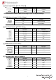
Chapter 1 Introduction AMB-N280S1 Series with Intel Atom N2800 processor is a multi-function Industrial Main-board, which is suitable for using in all kind of applications. Besides basic I/O ports like VGA, HDMI, USB, COM. LAN, and GPIO. It also compliant with most industry standards for computing usage including CE and FCC. 1.1. Specifications CPU Chipset Display Memory Storage Ethernet Audio Serial Intel Atom N2800 Dual-core, clock speed 1.86G,TDP 6.5W Intel NM10,TDP 2.
1.2. Package Contents Check if the following items are included in the package.
Chapter 2 H/W Information This chapter describes the installation of AMB-N280S1. At first, it shows the Function diagram and the layout of AMB-N280S1. It then describes the unpacking information that you should read carefully, as well as the jumper/switch settings for the AMB-N280S1 configuration. 2.
Bottom Side 6 Intel N2800 CPU 1.86GHz Mini PCI-E1* Mini-PCIe Socket DIMM 1 204-Pin DDR3 Socket Intel NM10 PCH SIM Card slot Mini PCI-E2* Mini-PCIe Socket * The Mini-PCIE1 supports 3G module but cannot supports mSATA module. And Mini-PCIe2 supports mSATA module only.
2.
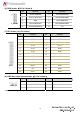
[1] Power Input Header(4*1 Pin 2.54mm) ATX1 Pin Definition Pin Definition 1 +12V IN 2 +12V IN 3 GND 4 GND * Please use the DC Power Cable in accessory to avoid the System damage. [2] CMOS Control Jumper (3*1 Pin 2.54mm) JCMOS1 Setting Function 1-2 Normal (Default) 2-3 Clear CMOS [3] Front Panel Header(5*2 Pin 2.54mm) F_PANEL1 Pin Definition Pin Definition 1 HD LED+ 2 3 HD LED- 4 5 GND 6 PW+ 7 RESET 8 PW- 9 N/C Power LED+ Power LED- [4] KBMS Header (6*1 Pin 2.
[6] GPIO Header(5*2 Pin 2.00mm) J_GPIO1 Pin Definition Pin Definition 1 GPIO6 (0500 Bit6) 2 GPIO22(0502 Bit6) 3 GPIO15 (0501 Bit7) 4 GPIO38(0x504 Bit6) 5 GND 6 GPIO7(0500 Bit7) 7 GPIO33(0504 Bit1) 8 GPIO36(0x504 Bit4) 9 GPIO39(0x504 Bit7) 10 +5V [7] LPT Header (13*2 Pin 2.
[9] LVDS Header(20*2 Pin 1.
[11] Serial Port 1-4 Header(20*2 Pin 2.0 mm) Pin 1 J_COM1-4 Definition DCD [2] Pin Definition 2 RXD 3 TXD 4 DTR 5 GND 6 DSR 7 RTS 8 CTS 9 RI 10 GND 11 DCD [2] 12 RXD 13 TXD 14 DTR 15 GND 16 DSR 17 RTS 18 CTS 19 RI [3] 20 N/A 21 DCD [2] 22 RXD 23 TXD 24 DTR 25 GND 26 DSR 27 RTS 28 CTS 29 RI [3] 30 GND 31 NC [4] 32 RXD 33 TXD 34 DTR 35 GND 36 DSR 37 RTS 38 CTS 39 NC [4] 40 GND [12] Serial Port 5 Header(3*1 Pin 2.
[14] Serial Port 6 Working Mode selection Header(two 3*1 Pin 2.54mm) Header Settings JP3 1-2 JP4 1-2 JP3 2-3 JP4 2-3 Working Mode RS-485 JP3、JP4 RS-232(Default) [15] RS485 Header(2*1 Pin 2.54mm) J485_1 Pin Definition Pin Definition 1 RS485+ 2 RS485- *Workable in RS-485 mode only [16] System Fan1 Header (3*1 Pin 2.54 mm) SYS_FAN1 Pin Definition Pin Definition 1 GND 2 + 12V 3 FANIO1 [17] System Fan2 Header (3*1 Pin 2.
[19] VGA Header(12*1 Pin 2.00 mm) J_VGA1 Pin Definition Pin Definition 1 CRT_ON 2 VSYNC 3 HSYNC 4 GND 5 RED 6 GND 7 GREEN 8 GND 9 BLUE 10 GND 11 DDCDAT 12 DDCCLK [21] ATX2 Power Output Header (4*1 Pin 2.54mm) ATX2 Pin Definition Pin Definition 1 +12V 2 GND 3 GND 4 +5V [22] SATA DOM Power Output Control Jumper JSATA1 (3*1 Pin 2.
Chapter 3 BIOS Settings This chapter describes the BIOS menu displays and explains how to perform common tasks needed to get the system up and running. It also gives detailed explanation of the elements found in each of the BIOS menus.
3.1. Main Setup Once you enter the AMI BIOS™ CMOS Setup Utility, the Main Menu will appear on the screen. Use the arrow keys to highlight the item and then use the keys to select the value you want in each item. Note: Listed at the bottom of the menu are the control keys. If you need any help with the item fields, you can press the key, and it will display the relevant information.
Project Version N/A This item displays the Project Information. Motherboard Version N/A This item displays the Mother Board Model. Built Data & Time N/A This item displays the Built information System Date N/A Set the date. Use Tab to switch between Date elements System Time N/A Set the time. Use Tab to switch between Date elements Access Level N/A Set the system access level.
3.2. Advanced Setup Option Choice Description ACPI Settings N/A ACPI Options Settings Power On N/A Power Fail settings CPU Configuration NA This item displays the CPU and Parameters. IDE Configuration N/A SATA and IDE port configuration. USB Configuration NA Monitor hardware status SMART Settings NA Power Sub System Super IO NA System Super IO Chip Parameters.
3.2.
3.2.2 Power On Configuration Option Choice PowerOn After Power On/ Power Power Fail Off / Last Status Description Define the system Power status after Power Fail.
3.2.3 CPU Configuration Option Choice Description Hyper-Threading Enabled / Disabled Enabled or Disabled the Hyper-Threading Technology.
3.2.4 IDE Configuration Option Choice SATA Controller(s) Enabled / Disabled SATA Mode Selection SATA Port 0 IDE / AHCI Enabled / Disabled SATA Port 0 Hot Plug Enabled / Disabled SATA Port 1 Enabled / Disabled SATA Port 1 Hot Plug Enabled / Disabled Description Enable or Disable SATA Device. Determines how SATA controller(s) operate.
3.2.5 USB Configuration Option Legacy USB Support EHCI Hand-Off Choice Description Enables Legacy USB support. AUTO option disables legacy Enabled / Disabled support if no USB devices are connected. DISABLE option will keep USB devices available only for EFI applications. Enabled / Disabled Enable or Disable the EHCI Hand-Off Function. It Could Disable if driver of OS is not supported.
3.2.
3.2.
3.2.7.
3.2.7.
3.2.
3.3.
3.3.
3.3.1.
3.3.
3.3.2.1 TPT Device Option Choice Azalia Controller Disable / HD Audio Select USB Mode USB Functions USB 2.
3.4.
3.4.
3.5.
3.6.
Chapter 4 Function Description 4.1. DC Power input connection AMB-N280S1 needs DC 12V to power the board. * Please use the DC Power Cable in accessory to avoid the System damage. 4.2. Digital Inputs There are 4 Digital Inputs you could use for many applications. 4.3. Digital Outputs There are 4 Digital Outputs you could use for many applications. 4.4. RS-232 Ports The COM1/COM2/COM3/COM4/COM5/COM6 are connected through a cable(pin header). Users need to plug into RS-232 or RS-485 connector.