ANR-IB75N1/A/B System Manual 1
Copyright All Rights Reserved. Manual’s first edition: For the purpose of improving reliability, design and function, the information in this document is subject to change without prior notice and does not represent a commitment on the part of the manufacturer. In no event will the manufacturer be liable for direct, indirect, special, incidental, or consequential damages arising out of the use or inability to use the product or documentation, even if advised of the possibility of such damages.
Table of Contents Chapter 1 Introduction ......................................................................... 5 1.1. System Specifications ........................................................................................................ 5 1.2. 1.3. 1.4. Packing List........................................................................................................................ 8 Features ...................................................................................................
5.2.4. Intel(R) 82576 Gigabit Dual Port Network Connection .......................... 44 5.2.5. Intel(R) 82574L Gigabit Network Connection .......................................... 45 5.3. HW Monitor Setup ........................................................................................................... 46 5.4. Chipset Setup ................................................................................................................... 47 5.4.1. USB Configuration ...............................
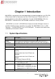
Chapter 1 Introduction ANR-IB75N1 is designed for rack-mounted platform for networking appliance, e.g. VPN, SSL, UTM or firewall. With 3rd Generation Intel Core i7/i5/i3 Processors / Pentium CPU, It is a powerful platform to satisfy different applications. By eight 10/100/1000Mbps LANs, the ANR-IB75N1 is sufficient for the small to middle size business security solution. ANR-IB75N1 can install 2 x HDD,BIOS and Jumper can control LAN bypass feature. It provides flexibility to access Internet by user setting.
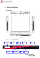
Network Interface Ethernet LAN by-Pass 8 * RJ45 and 0/2/4 * SFP 1. 2. LAN1/LAN2, LAN3/LAN4 support by-pass Reserve 1*3 pin Jumper for Hardware select bypass status I/O Front panel Internal I/O From left to right: 1. LCM module 2. Up, Down, Left, Right key pad 3. Reset Button 4. Power LED/HDD/bypass 1 & 2 : Green/Green/Yellow/Yellow 5. 0/2/4 * SFP (F1~F4) 6. COM port (RJ45) 7. 2 * USB 3.0 8. LAN 8/7/6/5/4/3/2/1 1. 2. 3. 4. 5. LCM pin header(7-pin pinhead 2.54mm ) ATX 24pin Power input 1*8 pin 2.
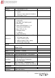
Temperature Storage Temperature -20~80oC (-4~176oF) Relative Humidity 0 to 90% @ 40°C, non-condensing Power supply Standard ATX power (250W~300W) Power Requirements ATX circuit as AT mode with power switch EMC & Safety EMC CE, FCC Class A Safety EN 60950-1:2006/A12:2011 7
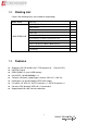
1.2. Packing List Check if the following items are included in the package. Model Name ANR-IB75N1/A/B 1.3.
1.4.
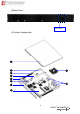
(3) Back Panel Power Inlet (4) System Configuration 1 2 9 3 4 5 6 10 7 8 10
Item Description Quantity 1 TOP COVER 1 2 POWER SUPPLY 1 3 BOTTOM BASE 1 4 POWER BRACKET 1 5 1U EAR BRACKET 2 6 HDD BRACKET 1 7 MEMBRANE 1 8 AMB-IB75N1/A/B 1 9 CPU Heatsink module 1 10 FAN 3 11
Chapter 2 Procedures of Assembly/Disassembly 2.1 2.5” HDD Installation The following instructions will guide you to install 2.5” HDD step-by-step. 1. Unfasten 2 screws of chassis top cover and take off it. 2. Release HDD bracket by unfastening 4 screws.
3. Take out HDD screws from packing bag. 4. Fix HDD with HDD bracket by 4 screws.
5. Fix HDD with HDD bracket by 4 screws.
6. Plug SATA power cable into motherboard. 7. The SATA power cable MUST go through below M/B power cable, please follow below photo.
8. Connect SATA cable and SATA power cable with HDD module. 9. Assemble top cover back by fastening the 2 screws.
2.2 CF Card Installation 1. Open the top cover (the same as above steps). 2. Push CF card into CF socket. 3. Finish the CF card installation.
2.3 Power Cord Hook Installation 1. Take out the hook from packing bag. 2. Install the hook from right side firstly. 3. Then install the hook by left side.
2.4 Rack Bracket Installation 1. Take out the screws and Rack bracket from packing bag. 2. Fixed the Rack bracket to Chassis by fastening 6 screws.
Board Guide 20
Chapter 3 Board Introduction AMB-IB75N1 is designed for rack-mounted platform for networking appliance, e.g. VPN, SSL, UTM or firewall. With 3rd Generation Intel Core i7/i5/i3 Processors / Pentium CPU, It is a powerful platform to satisfy different applications. By eight 10/100/1000Mbps LANs, the AMB-IB75N1 is sufficient for the small to middle size business security solution. AMB-IB75N1 can install 2 x HDD,BIOS, and Jumper can control LAN bypass feature.
3.2. Package Contents Check if the following items are included in the package.
3.3.
Chapter 4 H/W Information This chapter describes the installation of AMB-IB75N1/A/B. At first, it shows the Function diagram and the layout of AMB-IB75N1/A/B. It then describes the unpacking information which you should read carefully, as well as the jumper/switch settings for the AMB-IB75N1/A/B configuration. 4.1.
4.2.
4.3. Connector pin define 4.3.1. DDR3 DIMM Connector DIMM1 DIMM2 Standard DDR3 DIMM connector 4.3.2.
4.3.3. FAN Connector SYSFAN3 SYSFAN2 SYSFAN1 PIN Signal 1 2 GND +12V FAN Speed Detect 3 3 Pin, Pitch:2.54mm CPUFAN1 PIN Signal 1 2 GND +12V FAN Speed Detect FAN PWM Control 3 4 4 Pin, Pitch:2.54mm 4.3.4.
LAN1 RJ45 LAN Connector LAN2 RJ45 LAN Connector LAN3 RJ45 LAN Connector LAN4 RJ45 LAN Connector LAN5 LAN LED table: LED LED1 RJ45 LAN Connector LED2 LAN6 RJ45 LAN Connector LAN7 RJ45 LAN Connector LAN8 RJ45 LAN Connector ON/OFF Status OFF 10Mbps Green 100Mbps Orange 1000Mbps Yellow Link/Active OFF LAN OFF CN_2USB1 Standard USB 3.0 Type-A connector LED3 COM1 Green1: Power ON LED. Green2: HDD LED RS-232, RJ45 connector Yellow1: LAN3&LAN4 Bypass PIN LED.
LED2 RST1 UP : Green1: Link LED Push this button to reset the Yellow1: Active LED system. Down : Green2: Link LED Yellow2: Active LED CN3, CN4 LED1 Dual SFP Connector. UP : 1000BASE-SX/LX SMALL Green1: Link LED FORM-FACTOR Yellow1: Active LED PLUGGABLE (SFP) OPTICAL FIBER Down : TRANSCEIVER OR MINI-GBIC Green2: Link LED CONNECTOR 4.3.5.
4.3.6. ATX Power Connector & VGA Connector ATXPWR1 FP_VGA1 4.3.7. VGA Wafer Connector ATX12V1 ATX Power Supply Input ATX12V Power Input Other Connector JP2 (For LAN1/LAN2 Bypass Function Select.).
CPLD1 For CPLD Firmware Update PIN 1 3 5 7 (For LAN3/LAN4 Bypass Function Select.).
CCMOS1 CMOS Memory Clearing Header Extended Models Information Model Name Model Parts Difference Remark AMB-IB75N1 Intel GbE LAN x8 AMB-IB75N1A Intel GbE LAN x8 + 2 Fiber CN3 AMB-IB75N1B Intel GbE LAN x8 + 4 Fiber CN3 32 CN4
Chapter 5 BIOS Settings This chapter describes the BIOS menu displays and explains how to perform common tasks needed to get the system up and running. It also gives detailed explanation of the elements found in each of the BIOS menus.
5.1. Main Setup Once you enter the AMI BOS™ CMOS Setup Utility, the Main Menu will appear on the screen. Use the arrow keys to highlight the item and then use the <+> <-> keys to select the value you want in each item. Note: Listed at the bottom of the menu are the control keys. If you need any help with the item fields, you can press the key, and it will display the relevant information.
5.2. Advanced Setup Option Choice SATA Configuration N/A SATA Device Options Settings N/A System Super IO Chip Parameters.
5.2.1. SATA Configuration Option SATA Mode Selection Choice IDE / AHCI Description Determines how SATA controller(s) operate.
5.2.2.
5.2.2.1. COM1 Configuration Option Choice Description Auto IO=3F8h; IRQ=4 / IO=3F8h; IRQ=3,4,5,6,7,10,11,1 2 / IO=2F8h; Change Settings IRQ=3,4,5,6,7,10,11,1 2 / IO=3E8h; Select an optimal setting for Super IO device.
5.2.2.2.
Option Choice Serial Port Disabled / Enabled Description Enable or Disable Serial Port (COM) Auto IO=3F8h; IRQ=4 / IO=3F8h; IRQ=3,4,5,6,7,10,11,1 2 / IO=2F8h; Change Settings IRQ=3,4,5,6,7,10,11,1 2 / IO=3E8h; Select an optimal setting for Super IO device. IRQ=3,4,5,6,7,10,11,1 2 / IO=2E8h; IRQ=3,4,5,6,7,10,11,1 2 Standard Serial Port Mode / IrDA Active pulse 1.
5.2.3. Serial Port Console Redirection Option Choice Console Redirection Disabled / Enabled Console Redirection Settings EMS Description Console Redirection Enable or Disable. The settings specify how the host computer and the remote N/A computer (which the user is using) will exchange data. Both computers should have the same or compatible settings.
5.2.3.1.
Option Choice Description Emulation: ANSI: Extended ASCII char set. VT100: ASCII Terminal Type VT100 / VT100+ / char set. VT100+: Extends VT100 to support color, function VT-UTF8 / ANSI keys, etc. VT-UTF8: Uses UTF8 encoding to map Unicode chars onto 1 or more Bits per second 9600 / 19200 / Selects serial port transmission speed. The speed must be 38400 / 57600 / matched on the other side. Long or noisy lines may require 115200 Data Bits 7/8 lower speeds.
5.2.4. Intel(R) 82576 Gigabit Dual Port Network Connection Option Choice NIC Configuration N/A Click to configure the network device port. N/A Blink LEDs for the specified duration (up to 15 seconds).
5.2.5. Intel(R) 82574L Gigabit Network Connection Option Choice NIC Configuration N/A Click to configure the network device port. N/A Blink LEDs for the specified duration (up to 15 seconds).
5.3.
5.4.
5.4.1. USB Configuration Option xHCI Mode EHCI1 Choice Smart Auto / Auto / Disabled / Enabled Disabled / Enabled Description Mode of operation of xHCI controller. Control the USB EHCI (USB 2.0) functions. One EHCI controller must always be enabled.
5.5. Boot Setup Option Setup Prompt Timeout Boot up NumLock State Choice N/A ON / OFF Description Number of seconds to wait for setup activation key. 65535(0xFFFF) means indefinite waiting.
5.6. Security Setup option dministrator Password HDD module name Choice N/A N/A Description Set Administrator Password Set HDD Password (It will show the HDD model, if you have to join the HDD.
5.6.1. HDD Password Description option Choice Set HDD Password N/A Description Set HDD User Password.
5.7. Save & Exit Setup option Choice Description Pressing on Save Changes and Exit this item for save Exit system setup after saving the changes. changes and exit. Discard Changes and Exit Pressing on this item for discard Exit system setup without saving any changes. changes and exit. Pressing on this item for Save Changes confirmation : Save Save Changes done so far to any of the setup options..
Pressing on this item for Discard Changes confirmation: Load Discard Changes done so far to any of the setup options. Previous Values Pressing on this item for Restore Defaults confirmation: Load Optimized Defaults Restore/Load Default values for all the setup options. Pressing on Save as User Defaults this item for confirmation: Save Save the changes done so far as User Defaults.
Chapter 6 Driver And Utility Installation 6.1. Driver CD Interface Introduction Acrosser provides the a driver CD, which includes the drivers, utilities, applications and documents. For Windows environment, it can be guided by the setup program; for Linux environment, the related files can be found at folder “IB75N1\Linux”. Once putting the CD into the optical disk drive, it will run automatically. The driver CD will also detect the MB information to see if they are matched.
6.1.1 Driver Page This is the Driver Installation Page.
Click the icon, all the drivers will be selected.
Click the icon, all selected items will be cleared.
Click the icon to install the selected drivers. The progress bar shows up. The main window will temporarily disappear.
Please click ‘Yes’ to restart the system.
Click this icon to browse this CD content.
6.1.2 Utility Page Note: For Testing utility running completely, it should be run at test-signed kernel-mode under Operating System x64 edition. “BCDEdit /set testsigning on” is the introduction to run at command mode which turns test-signed kernel-mode to on. Please refer to MSDN by following URL for more detail. http://msdn.microsoft.com/en-us/library/windows/hardware/ff542202(v=vs.85).
LAN Bypass APIs Test Utility LCM Test Utility 62
Watch Dog Test Utility Sample code 63
6.1.
6.1.4 Documents Page Double click on one of the items to open the manual.
Chapter 7 Software Installation and Programming Guide 7.1. Introduction 7.1.1 LCD Control Module The LCM (short for LCD Control Module) APIs provide interfaces to control the module. By invoking these APIs, programmers can implement the applications which have the functions listed below: 1. 2. 3. 4. 5. 6. Clear LCD screen. Turn on or off the cursor on the screen. Move the cursor on the screen. Turn on or off the text on the screen. Get the identification of the pressed key of the LCM.
7.1.4 IB75N Library (Window platform only) The released code for Windows platform includes a folder called ‘AMB-IB75N1’. In this folder, there are header files and source codes of all the APIs of LCM module, Watchdog, and LAN Bypass functions. The source codes in this folder generate the API library ‘IB75N.lib’ and ‘IB75N.dll’. Users who want to invoke the APIs can include the ‘IB75N.h’ in their application source code and compile their application with the library ‘IB75N.lib’ or ‘IB75N.dll’.
7.2.2 Watchdog On Linux platform: 1. Libw83627.h This file includes the declarations of the APIs and macro definitions. 2. maintest.c The source code of the utility. On Windows platform: 1. IB75N.h The header file of the APIs. 2. IB75N.lib and IB75N.dll The API libiaries. 7.2.3 LAN Bypass Subsystem On Linux platform: 1. bypass.h This file includes the declarations of the APIs and macro definitions. 2. main.c The source code of the utility. On Windows platform: 1. IB75N.h The header file of the APIs. 2.
7.3. API List and Descriptions 7.3.1 Type Definitions Typedef Typedef Typedef Typedef Typedef Typedef char unsigned char short unsigned short unsigned long int i8; u8; i16; u16; u32; i32; 7.3.2 LCD Control Module 1. i32 clrscrLcm( void ) Description: Clear the screen of the LCM. Return value: 0 after the screen is cleared. 2. i32 cursorLcm( bool mode ) Description: According to the argument ‘mode’, show the cursor on the LCM screen or eliminate the cursor on the LCM screen.
4. i32 displayLcm( bool mode ) Description: Show the text on the LCM screen or eliminate the text on the LCM screen. The content of the text is not altered. mode = true, show the text. mode = false, eliminate the text. Return value: 0 after the text has been shown or eliminated. 5. i32 getKeyLcm( void ) Description: Scan the LCM and return the identification of the pressed direction key. Return value: ‘UP’ if the ‘up’ direction key is pressed. ‘RIGHT’ if the ‘right’ direction key is pressed.
7.3.3 Watchdog 1. Syntax: Void wdt_start(int, int) Description: This function read the value of the watchdog time counter and return it to the caller. Parameters: None. Return Value: This function return the value of the time counter and return it to the caller as an unsigned integer. 2. Syntax: Void wdt_stop(void) Description: close watch dog timer. Parameters: None. Return Value: None. 3. Syntax: Int get_wdt_count(void) Description: This function get WDT_Counter. Parameters: None. Return Value: None. 7.
5. void forceBypass(void) Force the port to become bypass state. 6. void setWdt4(void) Set the watchdog timer to 4 seconds. 7. void setWdt8(void) Set the watchdog timer to 8 seconds. 8. void setWdt16(void) Set the watchdog timer to 16 seconds. 9.
FAQ There are 2 kinds of SATA modes --- AHCI & legacy IDE mode. When you use the Linux, We strongly suggest to use AHCI mode. For legacy IDE mode, we found some SATA HDD could have compatibility issue. Please confirm the BIOS setting is correct, thank you. Does my system support Windows 8? The system is designed and verified with Windows 7, Fedora 14 and Ubuntu 10. But, we did not verify this system with Windows 8. Please check with Acrosser local sales rep.
(reference only) Ensure the Network Connections/Local Area Connection is enabled (right click and choose “Enable”). If the problem persists, please turn off firewall and anti-virus S/W. If the problem still exists, please contact local FAE or service center for tests. (reference only) If the Network Connections/Local Area Connection is showed “limited connection” (yellow exclamation mark), please disable and enable your connection to fix this problem.
Appendix: Technical Support Form We deeply appreciate you purchase Acrosser products. Please find “tech_form.doc” file in our utility CD. If you have any questions or problems about Acrosser products, please fill in the following information: We will answer your questions a.s.a.p. 1) Describe your info and system info A. Your company name: _____________ B. Your contact info: _________________ & phone number: _________________ C. Your e-mail address: ______________________ D.
Acrosser Headquarters 新北市三重區重新路五段609巷12號10樓 10F., No.12, Lane 609, Sec. 5, Chongsin Rd., Sanchong District, New Taipei City 241, Taiwan, R.O.C. TEL: +886-(0)2-2 9999 000 FAX: +886-(0)2-2999-2887 acrosserinfo@acrosser.com Acrosser Taichung Office 台中市南屯區河南路四段162號12樓之6 12-6, No.162, Sec. 4, Henan Rd., Nantun Dist., Taichung City 408, Taiwan R.O.C.