
Instruction Manual


AR-B1042 User’s Guide
3-1
3. CRT/LCD FLAT PANEL DISPLAY
This section describes the configuration and installation procedure using LCD and CRT display.
z Board Installation
z Connecting the CRT Monitor
z LCD Flat Panel Display
z Supported LCD Panel
z Inverter Board Description
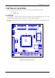
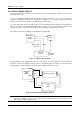
3.1 BOARD INSTALLATION
After setting the board’s jumpers, install the AR-B1042 module as follows:
Step 1 :
Make sure that the power to the system is off.
Step 2 :
Locate the PC/104 bus connector on the AR-B1042 VGA module and its counterpart on the CPU
card.
Step 3 :
Align the PC/104 bus connector pins on the AR-B1042 module with the CPU’s connector and gently
press the two cards firmly together.
Step 4 :
Fasten the two cards together with the screws.
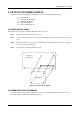
Acrosser's
CPU Card
AR-B1042
Figure 3-1 LCD Panel Block Diagram
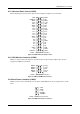
3.2 CONNECTING THE CRT MONITOR
To connect a CRT monitor, an adapter cable has to be connected to the CON2 (10-pin header type) connector.
This adapter cable is included in your AR-B1042 package.