AR-B1042 PC/104 VGA/LCD DISPLAY MODULE User’ s Guide Edition: 1.4 Book Number: AR-B1042-99.
AR-B1042 User¡¦s Guide Table of Contents 0. PREFACE....................................................................................................................................................... 0-2 0.1 0.2 0.3 0.4 0.5 0.6 0.7 1. OVERVIEW..................................................................................................................................................... 1-1 1.1 1.2 1.3 1.4 2. COPYRIGHT NOTICE AND DISCLAIMER .......................................................
AR-B1042 User¡¦s Guide 0.PREFACE 0.1 COPYRIGHT NOTICE AND DISCLAIMER January 1999 Acrosser Technology makes no representations or warranties with respect to the contents hereof and specifically disclaims any implied warranties of merchantability or fitness for any particular purpose.
AR-B1042 User¡¦s Guide 0.6 ORGANIZATION This information for users covers the following topics (see the Table of Contents for a detailed listing): l l l l l Chapter 1, “Overview”, provides an overview of the system features and packing list. Chapter 2, “Setting Up the System”, describes how to adjust the jumper, and the connectors setting. Chapter 3, “CRT/LCD Flat Panel Display”, describes the configuration and installation procedure using LCD display.
AR-B1042 User¡¦s Guide 1. OVERVIEW This chapter provides an overview of your system features and capabilities. The following topics are covered: l l l l Introduction Packing List AR-B1042 and Accessory List Features 1.1 INTRODUCTION The AR-B1042 is a PC/104 form factor super VGA controller for CRT and LCD display. It supports CRT color monitor, STN, Dual-Scan, TFT, monochrome and color panels. It can be connected to create a compact video solution for the industrial environment.
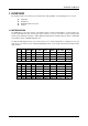
AR-B1042 User¡¦s Guide Model# Color Text Font Pixel Display (Hex) Display Size Resolution Mode 20 16 80x30 22 16 24 24I 30 16 16 256 32 34 8x16 Dot Clock Horizontal Vertical (MHz) Freq. (KHz) Freq. (Hz) 640x480 Note 3 56/25.175 31.5 60 100x37 8x16 800x600 Note 3 56/40.000 37.5 60 128x48 8x16 128x48 8x16 80x30 8x16 1024x768 1024x768 640x480 Note 3 Note 3 Note 1 65/65.000 65/44.900 56/25.175 48.5 35.5 31.
AR-B1042 User¡¦s Guide 1.3 AR-B1042 AND ACCESSORY LIST The AR-B1042 is a PC/104 form factor supports VGA controller for CRT or LCD display, it is very suitable for different types of monitors like the CRT monitor, STN, Dual-scan, TFT, Monochrome and color panels. With 512KB (or 1MB) of RAM on board, it allows a maximum CRT resolution of 1024x768x256 an LCD resolution of 640x480x64K colors. It can be connected to create a compact video solution for industrial environment.
AR-B1042 User¡¦s Guide 2. SETTING UP THE SYSTEM This section describes pin assignments for system’ s external connectors and the jumpers setting. l l Overview System Setting 2.1 OVERVIEW The AR-B1042 is a PC/104 form factor super VGA controller for CRT and LCD display board. This section provides hardware’ s jumpers setting, the connectors’ locations, and the pin assignment. The Acrosser provides many various transfer boards for using, please contact the Sales department will get more information.
AR-B1042 User¡¦s Guide 2.2 SYSTEM SETTING Before installing the AR-B1042 VGA module, you should first configure the VGA board’ s hardware. This section describes how to make connections and configure the VGA board. You may find it is convenient to go through these sections first before installing the VGA board into the PC/104 interface. The AR-B1042 VGA module is a very versatile VGA controller that can be used for either CRT or LCD display.
AR-B1042 User¡¦s Guide 2.2.
AR-B1042 User¡¦s Guide 2.2.
AR-B1042 User¡¦s Guide (3) I/O Channel Signal Description Name Description BUSCLK [Output] The BUSCLK signal of the I/O channel is asynchronous to the CPU clock. RSTDRV [Output] This signal goes high during power-up, low line-voltage or hardware reset SA0 - SA19 The System Address lines run from bit 0 to 19.
AR-B1042 User¡¦s Guide Name Description -MASTER [Input] The MASTER is the signal from the I/O processor which gains control as the master and should be held low for a maximum of 15 microseconds or system memory may be lost due to the lack of refresh -MEMCS16 The Memory Chip Select 16 indicates that the present [Input, Open collector] data transfer is a 1-wait state, 16-bit data memory operation -IOCS16 The I/O Chip Select 16 indicates that the present data [Input, Open collector] transfer is a 1-wai
AR-B1042 User¡¦s Guide 2.2.
AR-B1042 User¡¦s Guide 3. CRT/LCD FLAT PANEL DISPLAY This section describes the configuration and installation procedure using LCD and CRT display. l l l l l Board Installation Connecting the CRT Monitor LCD Flat Panel Display Supported LCD Panel Inverter Board Description 3.1 BOARD INSTALLATION After setting the board’ s jumpers, install the AR-B1042 module as follows: Step 1 : Make sure that the power to the system is off.
AR-B1042 User¡¦s Guide 3.3 LCD FLAT PANEL DISPLAY This section describes the configuration and installation procedure using LCD display. Skip this section if you are using CRT monitor only. J5 is used to configure the BIOS default setting for different types of LCD panel. To set your system properly, configure you AR-B1042 VGA module for the right type of LCD panel you are using by opening or shorting the jumper located at the component side of the AR-B1042 module labeled as J5.
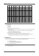
AR-B1042 User¡¦s Guide 3.4 SUPPORTED LCD PANEL At present, this VGA card can provide the total solution with inverter board for the following list of standard LCD panel using the PC/104 VGA module (AR-B1042). Consult your Acrosser representative for new developments, when using other models of standard LCD panels in the market. NO. Manufacture Model No. Description 1 2 NEC NEC NL-6448AC30-10 NL-6448AC32-10 TFT 9.4” TFT 10.2” 3 4 NEC HITACHI NL-6448AC33-10 LMG5371 TFT 10.4” MONO 9.
AR-B1042 User¡¦s Guide 4. INSTALLATION OF THE UTILITY SOFTWARE This chapter describes the installation of the utility software. The following topics are covered: l l l l Install Application Software The CHIPSDSP Utility Program The CHIPSCPL Utility Program The SETCOL Utility Program 4.1 INSTALL APPLICATION SOFTWARE 4.1.1 Windows 3.1 These drivers are designed to work with Microsoft Windows Version 3.1. You may install these drivers either through Windows or in DOS.
AR-B1042 User¡¦s Guide (4) Driver Installation – DOS Setup Step 1 : Install Windows as you normally would for a VGA display. Run Windows to make sure that it is working correctly. Then exit from Windows. Step 2 : Place the Display Driver Diskette #1 in drive A. Type A: to make this the default drive. Type SETUP to run the driver SETUP program. Press any key to get to the applications list. Using the arrow keys, select Windows Version 3.1 and press the key.
AR-B1042 User¡¦s Guide 4.1.3 AutoCAD R12 These drivers are designed to work with AutoCAD R12. They conform to the Autodesk Device Interface (ADI) for Rendering drivers and Display drivers. These display drivers accelerate redraw, pan, and zoom functions. (1) Driver Installation To install the drivers, follow these instructions: Step 1 : Place the Display Driver Diskette #1 in drive A. Type A: to make this the default drive. Type SETUP to run the SETUP program.
AR-B1042 User¡¦s Guide If you have previously installed a driver different from the TurboDLD driver, please note the following: After installing the TurboDLD Classic, when running the Render Command, AutoCAD R12 will take you into AVE_RENDER to reconfigure Render for your new driver. 4.1.4 Lotus 1-2-3 Lotus Symphony These drivers are designed to work with Lotus 1-2-3 Version 2.0, 2.01 and 2.02, and with Lotus Symphony Version 1.0 and 1.1.
AR-B1042 User¡¦s Guide 4.1.5 Word These drivers are designed to work with Microsoft Word Version 5.0 and 5.5. If you have already installed Word on your computer go to Step 2 install the new video driver. Step 1 : Install Word as you normally would. Step 2 : After you complete the Word installation, place the Display Driver Diskette #1 into drive A. Make A the default drive by typing A:. Run the SETUP program by typing SETUP . Press any key to display a list of supported applications.
AR-B1042 User¡¦s Guide 4.1.7 Windows NT These drivers are designed to work with Microsoft Windows NT 3.5x. Step 1 : Install Windows NT as you normally would for a VGA display. Run Windows NT Control Panel from the Main Group. Choose the Display option. In the Display Settings dialog box, click on Change Display Type. Click on Change from the Adapter Type in the Display Type dialog box. Click on Other in the Select Device dialog box. Step 2 : Place the Windows NT Display Driver Diskette in drive A.
AR-B1042 User¡¦s Guide 4.3 THE CHIPSCPL UTILITY PROGRAM This utility program is designed to work with Microsoft Windows Version 3.1. 4.3.1 Installing the Utility CHIPSCPL.CPL is a Windows based utility to select resolutions and color depth. It is a control Panel Applet with its own icon that is automatically installed when installing Chips Windows 3.1 Linear drivers. The Control Panel icon is in the Main Windows group. To invoke the control panel applet, simply click on the icon.
AR-B1042 User¡¦s Guide VERSION displays version information about the current driver. HELP displays help information on how to use the display Driver Control Panel. FONT SIZE (Japanese Windows only) allows you to select the font size from the following: • • • • 12 16 20 24 NOTE: The CHIPSCPL will prompt for Windows 3.1 and/or Chips driver disk(s) if required files are missing. 4.
AR-B1042 User¡¦s Guide 4.4.2 How to Use the Utility The SETCOL utility program allows you to specity the number of rows and columns on the screen. You indicate these values to the SETCOL program by placing them after the name SETCOL on the command line.
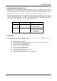
AR-B1042 User¡¦s Guide 5. ERROR (BEEP) CODES & INDEX 5.1 ERROR (BEEF) CODES There are three possible beep codes produced by the BIOS during POST listed below: Beep Code 1 long followed by 2 short beeps 1 long followed by 3 short beeps 1 long followed by 4 short beeps 1 long followed by 8 short beeps Table 5-5 Error (Beef) Codes Error Condition CMGA card failure RAM test failure DAC test failure VGA initialized failure If you have problems after installation, check the following to determine the cause. 1.