
User Manual


AR-B1047 User’s Guide
3-5
3.2.1 UV EPROM (27Cxxx)
(1) Switch and Jumper Setting
Step 1:
Use jumper block to set the memory type as ROM (FLASH).
Step 2:
Use jumper JP1 to select the correct EPROM type if 1Mx8 (27C080) EPROM is used.
Step 3:
Select the proper I/O base port, firmware address, disk drive number and EPROM type on SW1.
Step 4:
Insert programmed EPROM(s) or FLASH(s) chips into sockets starting at MEM1.
Step 5:
Line up and insert the AR-B1047 card into any free slot of your computer.
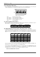
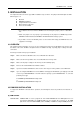
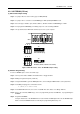
ON
12345678
OFF
Figure 3-1 UV EPROM (27CXXX) Switch Setting
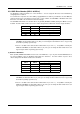
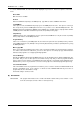
M1, M2, & M3
EPROM (128KX8, 256KX8 and 512KX8)
1
2
3
ABC
M1, M2, & M3
1
2
3
ABC
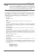
123
JP1
1MX8 EPROM (Only)
54
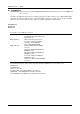
123
JP1
54
Figure 3-2 M1~M3 & JP1-3~JP1-5: UV EPROM Jumper Setting
(2) Software Programming
Use the UV EPROM, please refer to the follow steps:
Step 1:
Turn on power and boot DOS from hard disk drive or floppy disk drive.
Step 2:
Making a Program Group File (*.PGF file)
Step 3:
Using the RFG.EXE to generate ROM pattern files, and counting the ROM numbers as the pattern files.
Step 4:
In the DOS prompt type the command as follows.
C:\>RFG [file name of PGF]
Step 5:
In the RFG.EXE main menu, choose the <Load PGF File> item, that is user editing *.PGF file.
Step 6:
Choose the <Generate ROM File(s)>, the tools program will generate the ROM files, for programming the
EPROMs.
Step 7:
Program the EPROMs
Using the instruments of the EPROM writer to load and write the ROM pattern files into the EPROM chips.
Make sure that the EPROMs had been verified by the programming without any error.