AR-B1520 User’s Guide AR-B1520 INDUSTRIAL GRADE CPU BOARD User’ s Guide Edition: 1.0 Book Number: AR-B1520-05.
AR-B1520 User’s Guide Table of Contents 0. PREFACE …………………………………………………………………………………………………………………………3 0.1 COPYRIGHT NOTICE AND DISCLAIMER..................................................................................................................................3 0.2 WELCOME TO THE AR-B1520 CPU BOARD.............................................................................................................................3 0.3 BEFORE YOU USE THIS GUIDE ....................................................
AR-B1520 User’s Guide 0. PREFACE 0.1 COPYRIGHT NOTICE AND DISCLAIMER This document is copyrighted, 2002, by Acrosser Technology Co., Ltd. All rights are reserved. No part of this manual may be reproduced, copied, transcribed, stored in a retrieval system, or translated into any language or computer language in any form or by any means, such as electronic, mechanical, magnetic, optical, chemical, manual or other means without the prior written permission or original manufacturer.
AR-B1520 User’s Guide 0.6 STATIC ELECTRICITY PRECAUTIONS Before removing the board from its anti-static bag, read this section about static electricity precautions. Static electricity is a constant danger to computer systems. The charge that can build up in your body may be more than sufficient to damage integrated circuits on any PC board. It is, therefore, important to observe basic precautions whenever you use or handle computer components.
AR-B1520 User’s Guide 1. INTRODUCTION Welcome to the AR-B1520 PC104 Plus Single Embedded Board Computer. AR-B1520 supports SIS550 (a high performance/low cost SoC(System on Chip) solution by integrating an x86 compatible processor, high performance North Bridge, advanced hardware GUI engine and Super South Bridge). In addition, the AR-B1520 provides on chip VGA. The VGA, which provides up to True Color (32 bit) 1024x768, or High Color (16 bit) 1280x1024 resolution. The VGA memory is share main memory.
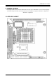
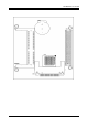
AR-B1520 User’s Guide 2. INSTALLATION This chapter describes how to install the AR-B1520. At first, the layout of AR-B1520 is shown, and the unpacking information that you should be careful is described. The following lists the jumpers and switches setting for the AR-B1520’s configuration. 2.
AR-B1520 User’s Guide 7
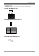
AR-B1520 User’s Guide 3. CONNECTION This chapter describes how to connect peripherals, switches and indicators to the AR-B1520 board. 3.1 POWER ON CONNECTOR (PWR) 4 1 PIN 1 Signal VCC(+5V) 2 GND 3 GND 4 +12V 3.2 KEYBOARD & MOUSE CONNECTOR (PS/2) 1 6 PS/2 PIN 1 2 3 4 5 6 SIGNAL MSDATA KBDATA GND VCC MSCLOCK KBCLOCK 3.3 CPU FAN POWER CONNECTOR (FAN) ※ This is a usual FAN, can’t scout function 1. +5V 2. +12V 3 1 3.
AR-B1520 User’s Guide 3.
AR-B1520 User’s Guide 3.
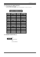
AR-B1520 User’s Guide 3.8 USB CONNECTOR (USB) 2 10 1 1. VCC 2. VCC 3. DATA1- 4. DATA0- 5. DATA1+ 6. DATA0+ 9 7. GND 9. GND 8. GND 10. GND 3.9 GPIO CONNECTOR (GPIO) 2 8 1. GPIO 0 5. GPIO 4 2. GPIO 1 6. GPIO 5 1 3. GPIO 2 7. GPIO 6 7 4. GPIO 3 8. GPIO 7 3.10 RESET CONNECTOR (RST) 1 PIN 1 2 2 SIGNAL RST GND 3.11 CLEAR CMOS (CMOS) PIN 1 3 CMOS FUNCTION 2-3 ON Normal Operation (Factory Preset) 1-2 ON Clear CMOS 3.
AR-B1520 User’s Guide 3.13 COM2 RS-232/RS-485 SELECT (P2,P3) JUMPER 5 3 1 FUNCTION P2 RS-485 P3 5 3 1 P2 RS-232 FACTORY PRESET P3 3.14 RS-485 TERMINATOR SELECT (JP2) When there is only one line the setting should be left off, if multiple blocks are used on a single line. This should be set to “ON” in order to properly terminate the connection for better transmission of data 1 2 Open 1 2 Closed Factory Preset 3.15 RS-485 HEADER (JP3) 1 2 3 1 N485+ 2 N4853 GND 3.
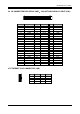
AR-B1520 User’s Guide 3.20 LCD CONNECTOR (LCD) 2 50 51 1 PIN 1 4 7 10 13 16 19 22 25 28 31 34 37 40 43 46 49 SIGNAL VVBD2 (B2) LLD7 (R3) VVBD5 (B5) UUD2 (R6) VVBD8 (G0) VVBD1 (B1) VVBD10 (G2) UUD5 LLD1 (G5) MOD LLD4 SHFCLK N.C GND +5V XCLK +12V PIN 2 5 8 11 14 17 20 23 26 29 32 35 38 41 44 47 50 SIGNAL LLD6 (R2) VVBD4 (B4) UUD1 (R5) VVBD7 (B7) VVBD0 (B0) LCDVDD UUD4 LLD0 (G4) UUD7 LLD3 (G7) VSYNC N.C N.
AR-B1520 User’s Guide 4. WATCHDOG TIMER This section describes the use of Watchdog Timer. AR-B1520 is equipped with a programmable time-out period watchdog timer that enable user to reset the system after a time out occur. Users can use simple program to enable the watchdog timer, and program the timer in range of seconds or minutes, with maximum 255 seconds/minutes.
AR-B1520 User’s Guide 5. BIOS CONSOLE This chapter describes the AR-B1520 BIOS menu displays and explains how to perform common tasks needed to get up and running, and presents detailed explanations of the elements found in each of the BIOS menus. The following topics are covered: Main Advanced Peripherals PnP/Pci Boot Exit 5.
AR-B1520 User’s Guide Date & Time Setup Highlight the field and then press the [Page Up] /[Page Down] or [+]/[-] keys to set the current date. Follow the month, day and year format. Highlight the
AR-B1520 User’s Guide Quick Power on Self Test This category speeds up Power On Self Test (POST) after you power on the computer. BIOS will shorten or skip some check items during POST. If it is set to Enabled, USB Controller This option can enable USB Ports or Disabled USB function. USB Keyboard Support This option can enable or Disabled USB keyboard function. CRT This option can enable VGA for CRT or Disabled CRT function. LCD This option can enable VGA for LCD or Disabled LCD function.
AR-B1520 User’s Guide 5.3 PERIPHERALS SETUP This option controls the configuration of the board’s chipset. Control keys for this screen are the same as for the previous screen. Peripherals Setup OnBoard Serial Port 1 OnBoard Serial Port 2 OnBoard Serial Port 3 OnBoard Serial Port 4 These options enable the serial port 1,2,3,and 4 on the AR-B1520 . UART Mode Select The item allows you to determine which InfraRed (IR) function of the onboard I/O chip, this function uses.
AR-B1520 User’s Guide 5.4 PNP/PCI SETUP The menu allows you to select enable or disable reset extend system configuration data(ESCO).
AR-B1520 User’s Guide 5.5 BOOT SETUP The Boot menu allows you to select among the four possible types of boot devices listed using the up and down arrow keys. Promotion or demotion of device alters the priority which the system uses to search for a boot device on system power up. Boot Setup First Boot Device Second Boot Device Third Boot Device Boot Other Device These options determine where the system looks first for an operating system.
AR-B1520 User’s Guide 5.6 EXIT SETUP When you have made all of your selections from the various menus in the step program, save your changes and exit Step. Select Exit from the menu bar by to display the following menu. Exit Setup NOTE:Pressing does not immediately exit this menu. Select one of the options from this menu or from the legend bar to exit this menu.
AR-B1520 User’s Guide 5.7 BIOS UPDATE The BIOS program instructions are contained within computer chips called FLASH ROMs that are located on your system board. The chips can be electronically reprogrammed, allowing you to upgrade your BIOS firmware without removing and installing chips. The AR-B1520 provides the FLASH BIOS update function for you to easily to update to a newer BIOS version. Please follow these operating steps to update to new BIOS: Step 1: Turn on your system and don’t detect the CONFIG.
AR-B1520 User’s Guide APPENDIX A.
AR-B1520 User’s Guide APPENDIX B.