
User Manual


AR-B1550 User’s Guide
8
Real-Time Clock & Non-Volatile RAM
2.4.3 Timer
The AR-B1550 provides three programmable timers, each with a timing frequency of 1.19 MHz.
Timer 0 The output of this timer is tied to interrupt request 0. (IRQ 0)
Timer 1 This timer is used to trigger memory refresh cycles.
Timer 2 This timer provides the speaker tone.
Application programs can load different counts into this timer to generate various sound frequencies.
2.5 SERIAL PORT
The ACEs (Asynchronous Communication Elements ACE1 to ACE4) are used to convert parallel data to a serial
format on the transmit side and convert serial data to parallel on the receiver side. The serial format, in order of
transmission and reception, is a start bit, followed by five to eight data bits, a parity bit (if programmed) and one,
1.5 (in a five-bit format only) or two stop bits(in a 6,7, or 8-bit format). The ACEs are capable of handling divisors of
1 to 65535, and produce a 16x clock for driving the internal transmitter logic.
Provisions are also included to use this 16x clock to drive the receiver logic. Also included in the ACE a completed
MODEM control capability, and a processor interrupt system that may be software tailored to the computing time
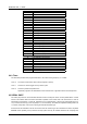
Address Description
00 Seconds
01 Second alarm
02 Minutes
03 Minute alarm
04 Hours
05 Hour alarm
06 Day of week
07 Date of month
08 Month
09 Year
0A Status register A
0B Status register B
0C Status register C
0D Status register D
0E Diagnostic status byte
0F Shutdown status byte
10 Diskette drive type byte, drive A and B
11 Fixed disk type byte, drive C
12 Fixed disk type byte, drive D
13 Reserved
14 Equipment byte
15 Low base memory byte
16 High base memory byte
17 Low expansion memory byte
18 High expansion memory byte
19-2D Reserved
2E-2F 2-byte CMOS checksum
30 Low actual expansion memory byte
31 High actual expansion memory byte
32 Date century byte
33 Information flags (set during power on)
34-7F Reserved for system BIOS