AR-B1622 User’s Guide AR-B1622 AMD GX3 , VGA , LAN , PC104+ , 2 COM , 4 USB User’ s Guide Edition: 1.
AR-B1622 User’s Guide 1. INTRODUCTION Welcome to the AR-B1622 Single Board Computer. The AR-B1622 board Low power GX3 series Processors with the advanced chipset CS5536. This product is designed for the system manufacturers, integrators, or VARs that want to provide all the performance, reliability, and quality at a reasonable price. In addition, the AR-B1622 provides on chip VGA. The VGA, which provides up to True Color (32 bit) 1024x768, or High Color (16 bit) 1280x1024 resolution.
AR-B1622 User’s Guide SPECIFICATIONS CPU: GX3 Chipset: CS5536 RAM memory: Supports DDR-RAM, on-board 200-pin SO-DIMM up to 1GB DDR-RAM memory module Display Interface: CRT –10-pin pin-header. LVDS – for 24 bit TFT LCD Panel. Ultra ATA/33/66/100 IDE Interface: Series ports: On-board two 2x5x2.00mm pin-header connector for COM1, COM2. USB port: Four USB 2.0 Ethernet: On-board one RTL8100C, supports 10/100Mbps Base-T with 1x7 2.00mm pin-header.
AR-B1622 User’s Guide 2. SETTING UP SYSTEM This chapter describes how to install the AR-B1622. At first, the layout of AR-B1622 is shown, and the unpacking information that you should be careful is described. Overview System Settings 2.
AR-B1622 User’s Guide Super I/O W83627 J1 BOTTOM PLACEMENT 5
AR-B1622 User’s Guide 2.2 SYSTEM SETTINGS Jumper pins allow you to set specific system parameters. Set them by changing the pin location of the jumper blocks. (A jumper block is a small plastic-encased conductor that slips over the pins.) To change a jumper setting, remove the jumper from its current location with your fingers or small needle-nosed pliers. Place the jumper over the two pins designated for the desired setting. Press the jumper evenly onto the pins. Be careful not to bend the pins.
AR-B1622 User’s Guide 2.2.2 VJP1 (LCD 3V or 5V) 1 PIN DEFINE 1-2 3V 3 2-3 5V 2.2.3 COM1&COM2 2 10 1 9 2.2.4 PIN DEFINE PIN DEFINE 1 -DCD 2 -DSR 3 SIN 4 -RTS 5 SOUT 6 -CTS 7 -DTR 8 -RI 9 GND 10 GND JFRT1 2 10 1 9 PIN DEFINE 1-2 RESET PIN 3:5V(PWR LED) PIN 4:GND PIN 5:5V PIN 6:HD LED PIN 7:SPEAKER+ PIN 8:SPEAKER- 3-4 5-6 7-8 9-10 2.2.
AR-B1622 User’s Guide 2.2.5 DIO1(GPIO) 2 10 1 9 2.2.6 PIN DEFINE PIN DEFINE 1 GND 2 5V 3 BIT 4 4 BIT 5 5 BIT 5 6 BIT 6 7 BIT 0 8 BIT 1 9 BIT 2 10 BIT 3 J5(PCI104) 1 2.2.7 1 6 A B C D NC SERIR +5V AD0 16 A B C D AD21 AD20 GND AD19 2 NC AD2 AD1 +5V 17 +3.3V AD23 AD22 +3.
AR-B1622 User’s Guide 2.2.8 USB1&USB2 2 10 1 9 2.2.9 PIN DEFINE PIN DEFINE 1 5V 2 5V 3 DATA- 4 DATA- 5 DATA+ 6 DATA+ 7 GND 8 GND 9 GND 10 GND BT1 2 1 2.2.10 2.2.11 1 PIN DEFINE 1 V+(3.
AR-B1622 User’s Guide 2.2.
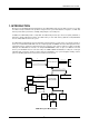
AR-B1622 User’s Guide 3. LCD FLAT PANEL DISPLAY This chapter describes the configuration and installation procedures for LCD displays. TFT LCD Interface LCD Panel AR-B1622 Backlight Power Inverter LCD Panel Block Diagram Please visit our web site or contact with our technical support department for supports of LCD connecting.
AR-B1622 User’s Guide 4. BIOS CONSOLE This chapter describes the AR-B1622 BIOS menu displays and explains how to perform common tasks needed to get up and running, and presents detailed explanations of the elements found in each of the BIOS menus. The following topics are covered: z z z z z BIOS Setup Overview Advanced CMOS Setup Peripheral Setup Boot BIOS Exit 4.
AR-B1622 User’s Guide Date & Time Setup Highlight the field and then press the [Page Up] /[Page Down] or [+]/[-] keys to set the current date. Follow the month, day and year format. Highlight the
AR-B1622 User’s Guide Console Redirection【Enable】 This allows you to enable the console function or not. Baud Rate【115200】 This allows you to set up the transfer speed for console. Agent after boot【Disabled】 This allows you to open the Agent after boot function or not. 4.
AR-B1622 User’s Guide 4.3 PERIPHERALS Peripherals Onboard Serial Port 1 [3F8/IRQ4] Choose serial port 1 I/O address. Do not set port 1, 2, 3 and 4 to the same address except for Disabled or Auto. Onboard Serial Port 2 [2F8/irq3] Choose serial port 2 I/O address. Do not set port 1, 2, 3 and 4 to the same address except for Disabled or Auto. USB 1.0/1.1 Controller [Enables] This should be enabled if your system has a USB installed on the system board and you want to use it.
AR-B1622 User’s Guide 4.4PnP/PCI PnP/PCI Reset Configuration Data [Disable] Normally, you leave this field Disabled. Select Enabled to reset Extended System Configuration Data (ESCD) when you exit Setup if you have installed a new add-on and the system reconfiguration has caused such a serious conflict that the operating system cannot boot. Resources Controlled By [Auto (ESCD)] This field sets control over the IRQ resources by the automatic (ESCD) system or manual assignment of IRQ channels.
AR-B1622 User’s Guide 4.5 BOOT BOOT First/Second/Third Boot Device HDD-0 SCSI CDROM HDD-1 USB-FDD USB-ZIP USB-CDROM USB-HDD LAN Disabled Boot Other Device [Enabled] Configuration options: [Enabled] [Disabled]. LAN Boot Select [Disabled] This allows you to enable or disable the LAN Boot function..
AR-B1622 User’s Guide 4.6 BIOS EXIT Exit When you have made all of your selections from the various menus in the Setup program, save your changes and exit Setup. Select Exit from the menu bar to display the following menu. Save & Exit Setup Type “Y” will quit the Setup Utility and save the user setup value to RTC CMOS. Type “N” will return to Setup Utility. . Load Optimized Defaults Selecting this field loads the factory defaults for BIOS and Chipset Features, which the System automatically detects.
AR-B1622 User’s Guide 5. I/O address、IRQ and Memory Mapping 5.
AR-B1622 User’s Guide 5.2 IRQ Mapping 5.
AR-B1622 User’s Guide 6. GPIO Sample Code /*[]======================================================================[]*/ /*|| GPIO Test utility for W83627HF. ||*/ /*|| Date : 10/18/2005 ||*/ /*|| Author : Willy ||*/ /*[]======================================================================[]*/ /*[]======================================================================[]*/ /*|| Include files ||*/ /*[]======================================================================[]*/ #include
AR-B1622 User’s Guide if(Read_Byte&0x01) //GPI10 Show_Byte=Show_Byte|0x01; else if(Read_Byte&0x02) //GPI11 Show_Byte=Show_Byte|0x02; else if(Read_Byte&0x04) //GPI12 Show_Byte=Show_Byte|0x04; else if(Read_Byte&0x08) //GPI13 Show_Byte=Show_Byte|0x08; else if(Read_Byte&0x10) //GPI14 Show_Byte=Show_Byte|0x10; else if(Read_Byte&0x20) //GPI15 Show_Byte=Show_Byte|0x20; else if(Read_Byte&0x40) //GPI16 Show_Byte=Show_Byte|0x40; else if(Read_Byte&0x80) //GPI17 Show_Byte=Show_Byte|0x80; else Show_Byte=Show_Byte&0xFE
AR-B1622 User’s Guide printf("\n>>>>> GPI Test End return 0; // return pass <<<<<\n"); } /*[]======================================================================[]*/ /*|| Function : GPO_TEST() ||*/ /*|| Input : BYTE IO_PORT_BASE ||*/ /*|| Change :||*/ /*|| Return : Pass return "0", Fail return "1". ||*/ /*|| Description: Test GPO Pins status.
AR-B1622 User’s Guide { Show_Title(); return 1; } clrscr(); // Enter W83627HF Config Enter_Config(IO_PORT_BASE); Init_SIO(IO_PORT_BASE); switch(argv[1][0]) { case 'i': case 'I': //I Key result=GPI_TEST(IO_PORT_BASE); if(result==0) printf("Test Result is Pass."); else printf("Test Result is Fail."); break; case 'o': case 'O': //O Key result=GPO_TEST(IO_PORT_BASE); if(result==0) printf("Test Result is Pass."); else printf("Test Result is Fail.
AR-B1622 User’s Guide { int X_Axis,Y_Axis; char y_n; X_Axis=wherex(); /* Get Cursor X Axis */ Y_Axis=wherey(); /* Get Cursor Y Axis */ while(1) { y_n=getche(); if(y_n=='y' || y_n=='Y') return('y'); else if(y_n=='n' || y_n=='N') return('n'); else gotoxy(X_Axis,Y_Axis); } } /*[]======================================================================[]*/ /*|| Function : Enter_Config() ||*/ /*|| Input : BYTE IO_PORT_BASE ||*/ /*|| Change :||*/ /*|| Return : ||*/ /*|| Description: Enter chip configuration key.
AR-B1622 User’s Guide outportb(IO_PORT_BASE+1,0x07); // Set GPIO Port Active outportb(IO_PORT_BASE,0x30); outportb(IO_PORT_BASE+1,0x01); } 26